Hello,
I have the TI EVM3255 module that is not working and wondering if someone can help me troubleshoot the problem. I am a newbie in electronics and my knowledge is pretty much non-existent.
I bought the module but it was DOA. Texas Instruments sent me a replacement which is now working. I would like to fix the module rather than throwing it away. I need a subwoofer amp and this one will fit nicely.
When I turn on the amp, the FAULTz (D4) instantly lights up in red. No output at all when input and speakers are connected. Is it something that the faulty part/s can be identified? As someone who has zero knowledge, I do not know where to begin.
Any help is very much appreciated. Thanks!
TPA3255EVM Evaluation board | TI.com
Have you looked at the quick start guide?
FAULTz – indicates when a fault condition occurs (requires toggling reset to clear fault)
https://www.ti.com/lit/ml/slou458/s...=https%3A%2F%2Fwww.ti.com%2Ftool%2FTPA3255EVM
Have you looked at the quick start guide?
FAULTz – indicates when a fault condition occurs (requires toggling reset to clear fault)
https://www.ti.com/lit/ml/slou458/s...=https%3A%2F%2Fwww.ti.com%2Ftool%2FTPA3255EVM
Last edited:
I have a basic $15 meter, from Harbor Freight. Is that enough or do I need a more sophisticated one? I downloaded the User Manual from TI’s website and it has a schematic diagram. Although I must say, I do not have experience reading electronic schematic diagram, but willing to learn.
TPA3255EVM Evaluation board | TI.com
Have you looked at the quick start guide?
FAULTz – indicates when a fault condition occurs (requires toggling reset to clear fault)
https://www.ti.com/lit/ml/slou458/s...=https%3A%2F%2Fwww.ti.com%2Ftool%2FTPA3255EVM
I have tried it but no success. Will try again tomorrow.
What I would do is trace the signal from the input moving forward. Put a white noise signal on the amp in question and the one that works. Compare the signal at several points along the path.
How familiar are you with using your multi-meter? It's not a bad idea to insulate all of the probe, leaving only enough metal to touch your test points. It can save you from shorting one component to another.
If the surface mount components are too small, I'd think twice about checking the signal on the good board. U1 looks like it could be very precarious to test with a regular meter probe. It looks like it would be very easy to accidentally short two legs together. Do that and you might release the magic smoke") .
.
My method is far from ideal, but if you are determined to work on the bad amp and you don't have a schematic, it's the next best thing. However, do so at your own peril.
Mike
How familiar are you with using your multi-meter? It's not a bad idea to insulate all of the probe, leaving only enough metal to touch your test points. It can save you from shorting one component to another.
If the surface mount components are too small, I'd think twice about checking the signal on the good board. U1 looks like it could be very precarious to test with a regular meter probe. It looks like it would be very easy to accidentally short two legs together. Do that and you might release the magic smoke
.My method is far from ideal, but if you are determined to work on the bad amp and you don't have a schematic, it's the next best thing. However, do so at your own peril.
Mike
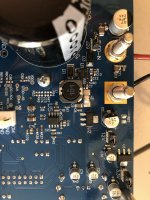
The things that go bad on these amps are usually the 15v DCDC buck converter U1 which is then regulated down to 12v and then again to 3.3v. The LDO's hardly ever fail unless over-voltage driven. Do you have steady 12v and 3.3v? This is indicated by two green LEDs. Sometimes the bootstrap cap C1 (o.047uF 100v X7R) on the buck converter goes bad so replace that to get the 15v output U1 working.
If the 12v and 3.3v LEDs are good, the other place to look at are blown bootstrap caps at the amp chip output. These are C27/29 & 52/54 0.033uF 100v X7R MLCC caps. Measure with an ohm meter across these and if one is shorted, replace it. Look for signs of burning.
Finally, the last thing that can be bad is the TPA3255 chip itself. If you have a hot air desoldering tool, remove the chip, clean the excess solder from the pads with copper wock, and replace with a new one using solder paste and hot air for $12.
That is about it.
Last edited:
Thank you for the advice. I am afraid the knowledgeWhat I would do is trace the signal from the input moving forward. Put a white noise signal on the amp in question and the one that works. Compare the signal at several points along the path.
How familiar are you with using your multi-meter? It's not a bad idea to insulate all of the probe, leaving only enough metal to touch your test points. It can save you from shorting one component to another.
If the surface mount components are too small, I'd think twice about checking the signal on the good board. U1 looks like it could be very precarious to test with a regular meter probe. It looks like it would be very easy to accidentally short two legs together. Do that and you might release the magic smoke
My method is far from ideal, but if you are determined to work on the bad amp and you don't have a schematic, it's the next best thing. However, do so at your own peril.
Mike
Thank you for the advice. I am afraid the knowledge and experience one must have as you just described, I do not have. I may just abandon fixing this unit.What I would do is trace the signal from the input moving forward. Put a white noise signal on the amp in question and the one that works. Compare the signal at several points along the path.
How familiar are you with using your multi-meter? It's not a bad idea to insulate all of the probe, leaving only enough metal to touch your test points. It can save you from shorting one component to another.
If the surface mount components are too small, I'd think twice about checking the signal on the good board. U1 looks like it could be very precarious to test with a regular meter probe. It looks like it would be very easy to accidentally short two legs together. Do that and you might release the magic smoke
My method is far from ideal, but if you are determined to work on the bad amp and you don't have a schematic, it's the next best thing. However, do so at your own peril.
Mike
Thank you very much for that easy to understand explanation. It gives me hope to resurrect the unit.The things that go bad on these amps are usually the 15v DCDC buck converter U1 which is then regulated down to 12v and then again to 3.3v. The LDO's hardly ever fail unless over-voltage driven. Do you have steady 12v and 3.3v? This is indicated by two green LEDs. Sometimes the bootstrap cap C1 (o.047uF 100v X7R) on the buck converter goes bad so replace that to get the 15v output U1 working.
If the 12v and 3.3v LEDs are good, the other place to look at are blown bootstrap caps at the amp chip output. These are C27/29 & 52/54 0.033uF 100v X7R MLCC caps. Measure with an ohm meter across these and if one is shorted, replace it. Look for signs of burning.
Finally, the last thing that can be bad is the TPA3255 chip itself. If you have a hot air desoldering tool, remove the chip, clean the excess solder from the pads with copper wock, and replace with a new one using solder paste and hot air for $12.
That is about it.
I will go through the steps you just described, beginning with the first one. I do not have extensive desoldering/soldering experience, let alone SMD soldering. However, my brother-in-law used to work on SMD board as his primary job. I will ask him if he can do it for me.
Thanks again, that is an excellent help!!!
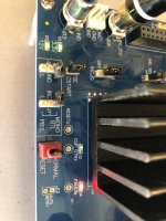
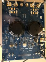
I tested the board again and the two green LED’s are on , including the FAULTz (red). See attached pics. I tried flipping the reset switch a few times but no luck, all lights are on. The red did not disappear as it should.The things that go bad on these amps are usually the 15v DCDC buck converter U1 which is then regulated down to 12v and then again to 3.3v. The LDO's hardly ever fail unless over-voltage driven. Do you have steady 12v and 3.3v? This is indicated by two green LEDs. Sometimes the bootstrap cap C1 (o.047uF 100v X7R) on the buck converter goes bad so replace that to get the 15v output U1 working.
If the 12v and 3.3v LEDs are good, the other place to look at are blown bootstrap caps at the amp chip output. These are C27/29 & 52/54 0.033uF 100v X7R MLCC caps. Measure with an ohm meter across these and if one is shorted, replace it. Look for signs of burning.
Finally, the last thing that can be bad is the TPA3255 chip itself. If you have a hot air desoldering tool, remove the chip, clean the excess solder from the pads with copper wock, and replace with a new one using solder paste and hot air for $12.
That is about it.
I then proceeded with the 2nd diagnosis as you suggested. Hard as I try, I cannot locate the C27/29 & C52/54. Am I missing something? I looked at both sides of the board but cannot find it. I looked several times. The only caps I saw are C26 & C25.
Attachments
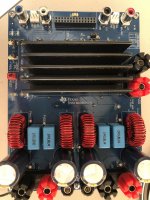
You have to remove the heatsink to get to the bootstrap caps as they are mounted very close to the pins on the chip. The red light constnatly on means something is bad, probably the bootstrap cap or a blown output MOSFET. In which case, replacing the TPA3255 is the only solution. It is fixable though and good clue that both 12v and 3.3v LEDs glow. Your power systems are good.
- Home
- Amplifiers
- Class D
- TI TPA3255 EVM - Need Help Troubleshooting