Hi guys,
I'm having an issue with a commercial guitar amp that uses the TDA 8954 Class D power amp chip.
Came in with a note stating "Do not turn on. Output Caps need attention".
Hmm.. So I took it apart and found that the output chokes had become desoldered due to excessive heat. I cleaned everything up and resoldered them back. Turned on and the amp works just fine - for about 5 minutes... Then it shuts down. Inspection reveals that the output chokes are getting VERY hot indeed, (even without input signal) so is the surrounding area on the PCB. Turn OFF and then wait a couple of minutes and the amp fires up ok but then shuts down after a minute or two.
Normal operation for an overheat condition I'm sure. The amp chip runs in bridge mode with the output connected to a single large speaker.
With no input connected to the amp there is a healthy sine wave on the output which is the same size both before and after the output filter. I'm assuming that the filter is not working (how much of the clock should I actually see at this point?).
Whilst I can see that this wave directly on the output audio is a bad idea from a speaker point of view I'm wondering why the amp shuts down and gets really hot. It's an 8ohm load but I would think that even with a bad filter, it should be able to cope with this. I've read some posts here about a 20uH filter not being large enough for an 8 Ohm load but I'm not sure if this is just someone's point of view or whether it's correct... ?? Supplies are + / - 40V so pretty standard for this design.
Since the amp works ok but "just" overheats I'm again assuming that the chip itself is ok so do you guys think that the only issue is the output filter itself? If so, I'll go ahead and replace all the filter components and see where we go - or do you think the overheating issue cause may be elsewhere?
I haven't done it already because the amp components are on both sides of the board, it's a real pain to take out (about 25 bolts and nuts to remove) and I can't operate it with the board out of its housing.
I'm unfamiliar with this particular chip so if anyone has worked with it could shed some light on the subject I'd be grateful.
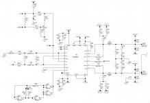
Pic included of the actual circuit I'm looking at.
Many thanks.
I'm having an issue with a commercial guitar amp that uses the TDA 8954 Class D power amp chip.
Came in with a note stating "Do not turn on. Output Caps need attention".
Hmm.. So I took it apart and found that the output chokes had become desoldered due to excessive heat. I cleaned everything up and resoldered them back. Turned on and the amp works just fine - for about 5 minutes... Then it shuts down. Inspection reveals that the output chokes are getting VERY hot indeed, (even without input signal) so is the surrounding area on the PCB. Turn OFF and then wait a couple of minutes and the amp fires up ok but then shuts down after a minute or two.
Normal operation for an overheat condition I'm sure. The amp chip runs in bridge mode with the output connected to a single large speaker.
With no input connected to the amp there is a healthy sine wave on the output which is the same size both before and after the output filter. I'm assuming that the filter is not working (how much of the clock should I actually see at this point?).
Whilst I can see that this wave directly on the output audio is a bad idea from a speaker point of view I'm wondering why the amp shuts down and gets really hot. It's an 8ohm load but I would think that even with a bad filter, it should be able to cope with this. I've read some posts here about a 20uH filter not being large enough for an 8 Ohm load but I'm not sure if this is just someone's point of view or whether it's correct... ?? Supplies are + / - 40V so pretty standard for this design.
Since the amp works ok but "just" overheats I'm again assuming that the chip itself is ok so do you guys think that the only issue is the output filter itself? If so, I'll go ahead and replace all the filter components and see where we go - or do you think the overheating issue cause may be elsewhere?
I haven't done it already because the amp components are on both sides of the board, it's a real pain to take out (about 25 bolts and nuts to remove) and I can't operate it with the board out of its housing.
I'm unfamiliar with this particular chip so if anyone has worked with it could shed some light on the subject I'd be grateful.
Pic included of the actual circuit I'm looking at.
Many thanks.
Attachments
Ferrite cored inductors can deteriorate with age and heat, making them less efficient, leading to more internal heating until this sort of failure.
So perhaps they need replacing with slightly more robust ones (higher current).
Also its worth checking what the oscillation frequency is. If the oscillator circuit is faulty this might have risen too high for the original inductors to handle (dissipation in ferrite rises with frequency typically).
So perhaps they need replacing with slightly more robust ones (higher current).
Also its worth checking what the oscillation frequency is. If the oscillator circuit is faulty this might have risen too high for the original inductors to handle (dissipation in ferrite rises with frequency typically).
With no input connected to the amp there is a healthy sine wave on the output which is the same size both before and after the output filter. I'm assuming that the filter is not working (how much of the clock should I actually see at this point?).
Something's amiss if the input to the filter's a sinewave. A classD amp puts out a PWM signal which will be a squarewave with no audio applied. The frequency I'd expect to be in the region of 300kHz or so. At the output there will be still some of this signal (commonly called the 'carrier') but usually 1V or thereabouts and it'll look much more like a sinewave.