Hi everyone,
I have been using GE FLTR100V20 75V 20A DC power filters in my class D amps for a while now with great success. They seem to clean up the SMPS noise very well.
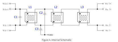
I am attaching the internal schematics extracted from the datasheet PDF Access Denied . I also labeled the components in the attached schematics (C1-C3, L1-L3).
What values for the inductors (L1-L3) and the capacitors (C1-C3) would you guys use if you had to implement this DC power filter on a prototype breadboard? Also, how would you improve it?
P.S. To be frank, I expected to see at least a couple of non-polar film/ceramic capacitors in there, but it appears that they are only using polar electrolytic capacitors.
I have been using GE FLTR100V20 75V 20A DC power filters in my class D amps for a while now with great success. They seem to clean up the SMPS noise very well.
I am attaching the internal schematics extracted from the datasheet PDF Access Denied . I also labeled the components in the attached schematics (C1-C3, L1-L3).
What values for the inductors (L1-L3) and the capacitors (C1-C3) would you guys use if you had to implement this DC power filter on a prototype breadboard? Also, how would you improve it?
P.S. To be frank, I expected to see at least a couple of non-polar film/ceramic capacitors in there, but it appears that they are only using polar electrolytic capacitors.
Attachments
Thanks for the reply. I would prefer to filter out as much noise as possible.
I have been also thinking about building a filter like this with three 50Watt 0.1Ohm resistors in place of the L1-L3 inductors. I believe that it would clean up the power coming from the rectifier/SMPS pretty good. What do you guys think?
I have been also thinking about building a filter like this with three 50Watt 0.1Ohm resistors in place of the L1-L3 inductors. I believe that it would clean up the power coming from the rectifier/SMPS pretty good. What do you guys think?
Hi everyone,
I have been using GE FLTR100V20 75V 20A DC power filters in my class D amps for a while now with great success. They seem to clean up the SMPS noise very well.
What values for the inductors (L1-L3) and the capacitors (C1-C3) would you guys use if you had to implement this DC power filter on a prototype breadboard? Also, how would you improve it?
P.S. To be frank, I expected to see at least a couple of non-polar film/ceramic capacitors in there, but it appears that they are only using polar electrolytic capacitors.
Since this filter is for DC, it can take advantage of higher capacitance from Electrolytic capacitors.
You can simulate filters with SPICE. One needs to consider what frequencies to be suppressed. The low frequency filter cutoff may depend on whether there a regulator driving it and the stability of the regulator with capacitive load.
I would not use resistors, instead of inductors, because then you just have an RC filter, instead of a LC filter, with which would be much more lossy and not as effective.
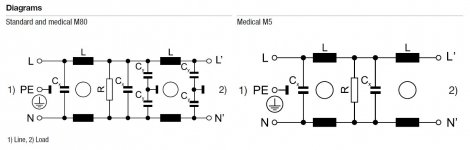
Here is an example common mode/differential mode CM/DM filter for 20A AC, with component values (no electrolytics), Schurter 3-123-525: https://www.mouser.com/ProductDetai...smHODk0kGqqY3D2smuu5IrW%2BcvTTYL7jFlKdchPBqRN
You May wish to go read this discussion thread on a differential mode (DM) 3A 50V DC filter: PO89ZB , an inline DC filter for SMPS wall warts . Preamps, HPA, Korg NuTube, etc
Attachments
Last edited:
Since this filter is for DC, it can take advantage of higher capacitance from Electrolytic capacitors.
You can simulate filters with SPICE. One needs to consider what frequencies to be suppressed. The low frequency filter cutoff may depend on whether there a regulator driving it and the stability of the regulator with capacitive load.
I would not use resistors, instead of inductors, because then you just have an RC filter, instead of a LC filter, with which would be much more lossy and not as effective.
....
Thank you so much for the information. I apologize for the late reply.
I agree that an RC filter would be much more lossy and not as effective as an LC filter. However, an inductor for an LC filter to clean up the noise from a transformer power supply would be very large and costly. This is one case where I would choose an RC filter over an LC filter. And it so happens that I need to clean up a couple of transformer power supplies (in addition to a bunch of SMPS bricks).
Thank you for the links. Unfortunately, I cannot see any component values in the datasheet PDF found at this link: https://www.mouser.com/ProductDetai...smHODk0kGqqY3D2smuu5IrW%2BcvTTYL7jFlKdchPBqRN . Am I looking in the wrong place?
What values for the inductors (L1-L3) and the capacitors (C1-C3) would you guys use if you had to implement this DC power filter on a prototype breadboard? Also, how would you improve it?
AC/DC doesn't really matter, as CM noise is AC. And since the DM flux for a CM filter is zero, the DC (or AC) input would literally be passed through, with only the CM noise returning to GND, via C2/C3.
Maximum values are 100nF X-cap (for preserving pf) and 4.7nF Y-cap (for limiting ground current), if used with AC. You may use higher X-cap values for DC, since the power factor then depends on the SMPS front-end (and not X-cap at its output). CM chokes are often used to clean up DC as well, so there's nothing wrong in doing so. A tighter coupling between the windings improves the filter.
All the best.
....
Thank you for the links. Unfortunately, I cannot see any component values in the datasheet PDF found at this link: 3-123-525 Schurter | Mouser . Am I looking in the wrong place?
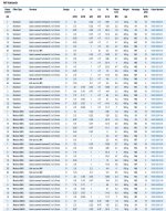
Many of the Shurter datasheets list the component values such as this one: 5500.2605.01 Datasheet (PDF)
Attachments
..... However, an inductor for an LC filter to clean up the noise from a transformer power supply would be very large and costly.....
If you are just filtering 60Hz or 120Hz rectified DC differential mode ripple from a simple AC mains transformer, then yes, the inductor size can be excessive. One can just drop a couple of volts in a series resistor.
Differential (Normal) Mode Noise and Common Mode Noise-Causes and Measures: Differential (Normal) Mode Noise and Common Mode Noise-Causes and Measures | Basic Knowledge | ROHM TECH WEB: Technical Information Site of Power Supply Design
The CM EMI filter is generally for incoming high frequency AC mains noise filtering. This why they are often configured as a panel box with a AC power cord connection. It is best to keep all the high frequency AC noise isolated external to the metal enclosure of the rest of the equipment. The CM EMI filter is encased in it's own metal enclosure, to isolate the AC RF noise. Sometimes feedthrough capacitors are used at entry (and sometimes the exit) points of the EMI filter.
If you are just filtering 60Hz or 120Hz rectified DC differential mode ripple from a simple AC mains transformer, then yes, the inductor size can be excessive.
Yes, it's CM noise you're filtering (and not DM ripple), so moving the CM filter to the AC side is not going to make things large or expensive.
Dear OP, please note that the CM rubbish in the windings have same direction and they add to give 4 times the inductance, while the DM noises have opposite directions and so they cancel (mostly), resulting in zero DM flux. In simple terms, the DM voltages see a short-circuit while the CM voltages see an LC filter.
Also note that your Y-capacitors need to be of the "fail-open" type in order to not cause heavy ground currents (risk of electric shock) during failure. However, the X-cap needs to fail short-circuited, readily blowing the fuse or tripping the breaker during failure.
AC/DC doesn't really matter, as CM noise is AC. And since the DM flux for a CM filter is zero, the DC (or AC) input would literally be passed through, with only the CM noise returning to GND, via C2/C3.
Maximum values are 100nF X-cap (for preserving pf) and 4.7nF Y-cap (for limiting ground current), if used with AC. You may use higher X-cap values for DC, since the power factor then depends on the SMPS front-end (and not X-cap at its output). CM chokes are often used to clean up DC as well, so there's nothing wrong in doing so. A tighter coupling between the windings improves the filter.
All the best.
Thanks so much!
Many of the Shurter datasheets list the component values such as this one: 5500.2605.01 Datasheet (PDF)
I see it now. Thank you!
If you are just filtering 60Hz or 120Hz rectified DC differential mode ripple from a simple AC mains transformer, then yes, the inductor size can be excessive. One can just drop a couple of volts in a series resistor.
Differential (Normal) Mode Noise and Common Mode Noise-Causes and Measures: Differential (Normal) Mode Noise and Common Mode Noise-Causes and Measures | Basic Knowledge | ROHM TECH WEB: Technical Information Site of Power Supply Design
The CM EMI filter is generally for incoming high frequency AC mains noise filtering. This why they are often configured as a panel box with a AC power cord connection. It is best to keep all the high frequency AC noise isolated external to the metal enclosure of the rest of the equipment. The CM EMI filter is encased in it's own metal enclosure, to isolate the AC RF noise. Sometimes feedthrough capacitors are used at entry (and sometimes the exit) points of the EMI filter.
Yes, among other things, I am trying to filter ripple from the AC mains transformer. Ideally, I want to have a DC power supply filter that will be able to filter out both Differential and Common Mode noise regardless of whether the power is supplied by a cheap SMPS or an AC mains transformer.
Those links were helpful, thank you.
U are filtering the DC rail in common mode instead of the AC input to meet regulations? What kind of "noise" are you experiencing? Seems very strange, to be honest...
Something like that. My oscilloscope died, so I cannot tell you exactly the kind of noise I am experiencing. I am trying to go above and beyond with filtering to try to eliminate as much noise as I possibly can.
- Home
- Amplifiers
- Class D
- Question about a 3-stage LC DC power filter