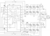
I usually deal with these car audio hip4080 designs via the car audio forum but most of us are Techs there and i'm hoping for the advice of someone that's designed a few 4080 based full bridge designs. I am attaching the relevant portion of the schematic and a datasheet for the OEM parts. The design is quite old and has been revised a few times but it did work as-is from the factory at one time.
The issue i'm having is i'm losing a lot of parts. The circuit originally uses the RFP40n10 but modern stock behaves abnormally in this circuit. We commonly use IRF3710z and generally don't have too many issues but recently that has changed as well. I'm not sure where changes are being made that's causing this but I can't find anything in the PCNs for the parts. Perhaps I should be looking at PCNs for the hip4080 instead.
I'm hoping someone can take a look at the circuit and suggest a modern MOSFET I can drop into this circuit reliably. The IRF3710z works fine on a resistive load up to 700 watts (My current bench capabilities). When I install it in a vehicle and introduce a 2 ohm reactive load and additional output yield the MOSFETS fail almost instantly. It's growing frustrating. I am using IR/Infineon parts from reliable distributors if that matters.
Full rail voltage is 80v and minimum impedance in 2 ohms. Feedback is pre-filter but I have omitted the feedback portion of the schematic.
Additionally if you can suggest why this may be happening for my own understanding, that would be appreciated. Suggested component changes are also appreciated.
Attachments
Curious what makes you suggest them? I can spec better MOSFETS in terms of power but there's a bit of calculating going on to select a drop-in replacement that works well in the application with no modifications to the drive and I honestly don't feel educated enough to determine that. Do you feel that part will work well in that instance?
Every time this amplifier fails I can lose up to 26 parts. I'm trying to avoid trial and error.
Thanks.
Every time this amplifier fails I can lose up to 26 parts. I'm trying to avoid trial and error.
Thanks.
Here's my analysis:
The HIP4080 seems to have programmable dead time upto only upto 120ns. You seem to be driving 3 FETs (which might total about 450nC of gate charge to switch) through a 100 ohm resistor. That's about 100mA maximum flow to charge up 450nC, which takes around 5 microseconds or so worst case (high drain current
means the gate charge is at a maximum, which is why reactive loads can exacerbate things).
The 1N4148 bypassing the 100 ohm resistor to speed up switch-off was essential to it functioning, yet the 1N4148 is not rated for the 3A+ current pulses the HIP4080 can deliver.
I suspect the failure mode is 1N4148 blows, switching off slows down leading to extreme shoot-through which pops all the MOSFETs.
When you parallel FET gates like this you need a separate resistor per gate to prevent oscillation modes and ensure they switch together rather than in sequence defined by their plateau voltages(*). 100 ohms is far too large for this application, maybe 10 ohms for each MOSFET, giving a switching time closer to what's needed. And at least a 1A rated ultra-fast diode (schottky perhaps) for the switch-off speed up, per MOSFET.
Note the suggested circuit in the 4080 datasheet shows no gate resistors at all.
That has some issues though, like pretty much guaranteeing cascade failure of the 4080 if the MOSFETs fuse.
(*) MOSFETs do most of the switching at the plateau voltage, which can vary +/-1V between devices - commoning the gates through a single resistor pretty much forces you to use matched batches of MOSFETs per bank to ensure one
doesn't hog all the current during the slow switch-on phase. Using separate
resistors ensures they all switch on in parallel. Switching faster anyway will reduce the problem, so 10 ohm resistors are good anyway.
[ BTW lose the decoupling caps on LDEL and HDEL, they are current inputs, not voltage inputs ]
And another thing - what are R35 and R51 doing? Normally you don't want any impedance between the source and the driver chip, especially inductive, but 1 ohms of resistance is probably bad news too.
And those snubbers, R24/C12, R69/C43 _definitely_ should not be that side of the 1 ohm resistors, that's really causing the 4080 to see bogus voltages, I presume they are to snub the MOSFET switching.
And of course make sure the bus never exceeds 80V under any circumstances (!)
And another thing the 4080 needs good __ceramic__ decoupling, say a minimum of 0.1µF and 10µF ceramic multilayer caps, with the 0.1µF closest to the power pin (a few mm at most), and the 10µF very close too. This is vitally important for all MOSFET driver chips, yet this circuit seems to only show an electrolytic which is beyond hopeless for high frequency high current decoupling (this chip switches many amps at extreme speed).
It should go without saying layout is important, with short, low-inductance paths for the connections between 4080 and the MOSFETs.
Last edited:
Mark,
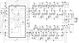
You seem to have a firm grasp on this design and I value your feedback. I have attached a revised design that was produced after this model. It produces more power (so there are more/different outputs) but you can see where they made some changes that you have already suggested. Interestingly though, they _increased_ the value of the gate resistors. I have no idea why the decoupling caps are across the DEL lines but other manufacturers have them as well despite it not being included in the datasheet documentation. Perhaps they're all just cloning a poor clone at this point.
Ideally, I'd like to have as little fly-wiring as possible going on due to the automotive environment and vibration. So foremost if it's possible to reuse existing component locations to make changes, that would be ideal. Point to point wiring 12 of everything is going to suck. I am using matched batch MOSFETs, if that helps. Unfortunately, I have to work best I can within the existing layout as the product is here and I have little control over that at this point.
Additionally the diode you mentioned doesn't always fail. But noted that it needs replaced with a better part. I'll hunt one down.
Is there a MOSFET you can suggest that will take the absolute worst this circuit has to offer reliably in a 220 package?
Attachments
Last edited:
Mark,
Unfortunately i'm stuck with what I have to work with here. The units we're built 20 years ago and I own 2 of them. I'd like to keep them. Automotive class D had a very rocky start for some brands and today things are much better. But I still have what I have here and I need to find a way to address it. It's a nostalgia thing for me and I can apply the knowledge to other repairs that come in.
I think I can reasonably manage *some* of the modifications you suggested. I've already performed some elsewhere in the amplifiers. Later 4080 models from other brands incorporated damper diodes across the outputs. Do you think there is a benefit to that worthwhile to bodging them in?
I still need to select a MOSFET.
Thanks.
- Status
- This old topic is closed. If you want to reopen this topic, contact a moderator using the "Report Post" button.
- Home
- Amplifiers
- Class D
- Need help selecting a good replacement MOSFET for 4080 full bridge design.