I wanted a schme as simple as possible and a power amplifier as easy as possible to make in amateur mode.(as a hobbyist).
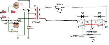
I used an SMPS push pull. ( with an transformer from an ATX computer power supply)
With the transformer secondary I directly in series the speaker and a solid state relay (Consisting of two NMOSFETs)
The audio PWM signal is given by an Attiny25 / 45 which also brings a lot of noise. I didn't solve the noise problem.
But I want to solve the following problem: So I use only half the power of the transformer.
When I need to have a positive voltage on the speaker, I waiting the positive pulse from the secondary and the voltage value is made of PWM duty.
I need an H-bridge-like circuit to change the polarity of the voltage, but to work and for positive voltage and for negative supply voltage.
Sure, I could put a rectifier bridge and an H-bridge, but there are too many components, I'm looking for something I can easily do.
Class D amplifier eliminated ultrafast bridge and SMPS filter capacitors - YouTube
I don't have an oscilloscope to show you the waveforms.
Calculated PWM frequency must be at 64KHz, but I didn't measure that, I just know it can't be heard.
Attachments
Last edited:
feeding the speaker with high frequency AC will output nothing, no matter what pwm you are switching. Anyway the high inductance of the speaker will allow only a very small current, but can create a high voltage eventually killing the mosfets.
Maybe some snubber could help there.
Maybe some snubber could help there.
Last edited:
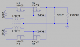
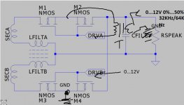
The scheme probably comes with too many warts but conceptually something like the attached. Two of your bi-directional switches one on each leg of a transformer secondary. Look up current doubler rectifier for what the filter inductor is about. You would wind it on a centre gapped E core one winding per side, not on top of each other, to introduce some equally divided leakage inductance. You drive the bidirectional switches in anti-phase from one pulse transformer with two secondaries as a 50% duty cycle square wave. You drive your primary side switches with 50% duty cycle square waves. You do not use pulse width modulation you achieve the audio modulation by varying the relative phase of those square waves. Good luck.
Attachments
I did say there would be worms. You place a couple of pairs of back to back zeners on the non grounded ends of the coupled inductor and accept some overlap whilst hoping the leakage inductance in that component saves the day. You also have to wonder what happens when the circuit undergoes regen from secondary to primary because leakage in the transformer is going to get in the way. Model it and see. The OP seems to have a working circuit despite all other concerns and caveats.
This is the easiest way: I attached the image.
The problem here is the driver for MOSFETS.
The usual optocoupler (CNY) is not fast enough, the IR21__ driver cannot be used, because the high side has high voltage but also positive and negative.
I could only use one transformer. T in the picture. I am thinking of a transformer (ferrite) with a section of 0.25cm2 with 20 primary turns and 20 secondary turns. If I have a simpler possibility to control the 2 NMOSFETs please let me know.
I thought of putting a bipolar transistor instead of a solid state relay(2xNMOSFTS). Using the bipolar transistor is in reverse active mode. But I concluded that it was a bad idea.
Attachments
Last edited:
As it sounds, there seem to be some discharges. Inductive cause.
In simple terms I give a rectangular pulse to the main transformer's primary.
The intensity of the current increases in the primary after an exponential, approximated with an inclined line
This increase in current in the primary also generates in the secondary a rectangular pulse voltage.
When it occurs in secondary coil consumption generates a secondary coil current and a magnetic field opposite to the primary.
According to Faraday u=-d magnetic flux/ dt, it should respond through voltage peaks to sudden changes in secondary consumption.
I could put zener, if they open at that switching speed, PN diodes.
Noise
But I noticed that the noise attenuates when I put LC filters on the audio input.
I wish I already had the sound, from an integrated bluetooth already in digital format.
Another weird idea.......
A step up SMPS, for example a Boost. From PWM to control the output voltage. And on the output a H bridge to change the polarity. Out between V+ and Vout.
The Boost output voltage has a more complicated dependence on the PWM duty cycle.
My intention was to make a simple and cheap subwoofer amplifier and not a great sound clarity.
Last edited:
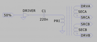
Uhm kind of but no. Use a single pulse transformer with two gate drive secondaries and a 50% duty cycle square wave drive on the primary. Picture... Note the phasing of the windings. SRCA and SRCB are the common source connections to your pairs of mosfets. Once again in order to modulate the thing you have to vary the phase of this drive compared to the 50% drive you supply to the switches on your main power transformer.
...
...
Attachments
Thank you very much,
I do not intend to keep the first Solid State relay open 50% of the time and the second relay 50%. I also need to create a variable voltage on the speaker so there will be a time when both relays are off.
Otherwise the variable voltage on the speaker should be created in "burst mode". But I think that makes even more noise.
Look at the complete thing assuming your main transformer is driven push pull with MOSA and MOSB. All drives are 50% duty cycle, no PWM. You do not want PWM. Forget about PWM.
When MOSA is on SECA produces a positive voltage. When MOSB is on SECB produces a positive voltage.
If SSRA is on at the same time as MOSA it will deliver a positive voltage to the load.
If SSRB is on at the same time as MOSB it will deliver a positive voltage to the load.
Alternatively
When MOSA is on SECB produces a negative voltage. When MOSB is on SECA produces a positive voltage.
If SSRA is on at the same time as MOSB it will deliver a negative voltage to the load.
If SSRB is on at the same time as MOSA it will deliver a negative voltage to the load.
With 50% duty cycle drive for all signals when in phase the output will be a 100% duty cycle positive voltage. With 50% duty cycle drive for all signals when out of phase the output will be a 100% duty cycle negative voltage.
As you vary the phase, secondary versus primary, from 0 degrees, in phase, to 180 degrees, out of phase, the output voltage will vary from fully positive to fully negative.
- Status
- This old topic is closed. If you want to reopen this topic, contact a moderator using the "Report Post" button.
- Home
- Amplifiers
- Class D
- I removed the rectifier bridge from the diagram - I'm looking for a simple schematic