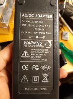
After my measurements on the A04 (https://www.diyaudio.com/forums/class-d/360821-aiyima-a04-tpa-3251-measurements-maybe.html), the manufacturer offered to send me a 07 amp for review. They also included a PSU in the 'kit'.
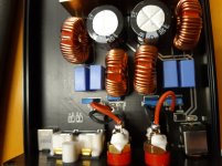
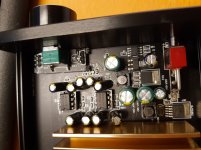
Below some pictures and scope shots.
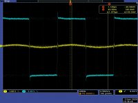
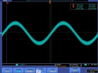
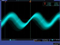
First scope pic is before and after output filter at idle, second is a 1k sine.
Will post measurements in next post.
Below some pictures and scope shots.
First scope pic is before and after output filter at idle, second is a 1k sine.
Will post measurements in next post.
Attachments
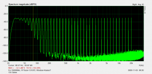
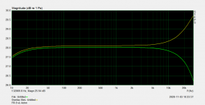
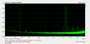
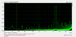
Measurements part 1
Attachments
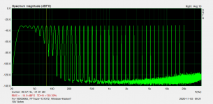
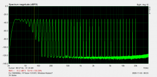
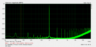

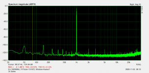
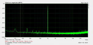
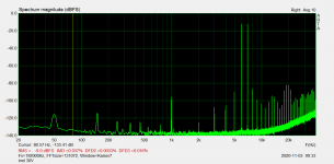
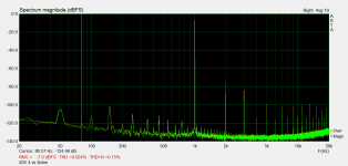
Measurements part 2, IMD.
All in all good measurement performance I would say. Frequency response is a bit of a output filter compromise for 4 and 8 ohms. Output filter seems well designed with no ringing etc.
There is increased distortion on high frequencies with high output levels, but distortion is still pretty low. I would guess due to some saturation in output inductors. PFFB would probably give an improvement on distortion and frequency response variations with load.
All measurements are 'as delivered' with the supplied PS, using the same Focusrite sound card as with the A04.
I have not listened to it yet, so I can't comment on the subjective sound.
Attachments
Hi,second is a 1k sine
really interesting to see those measurements. Do you really think the sine is supposed to look like that?
To me it looks like a bad match of output filter and load!?
This ~250kHz portion of the signal is pretty high in amplitude; not that it´s audible ;-)
Also what is this frequency? Half the PWM-frequency?
From your 2nd screenshot I count 20 periods within one division/200µs which would equate to ~100kHz, no?It's the switching frequency, and it seems to be abt 600kHz
(forget about the 250kHz in my first post)
So that is f_pwm.
f_osc should be 6xf_pwm=600kHz which is what we see in the first screenshot.
But these frequency ranges are not what is recommend for the chip, or?
(see page 7 of the datasheet)
Link to TI-forum with questions regarding setup of oscillator-frequency.
This one actually makes sense looking at your measurements but again, it´s not the same recommendations as page 7 in the datasheet!?
https://e2e.ti.com/support/audio/f/6/t/830552
Link to measurements from another design.
Quick Look: A Generic TPA3255 Design – QuantAsylum
Interesting how sensitive the chips are with regards to layout and also the quality of the digital supply. (not that it´s that surprising).
Last edited:
All I can do is offer another scope pic zoomed in, period time indicates abt 600kHz, so did the FFT on the scope, but the scope is old and the FFT is not good.
If you look at the square wave in the first post, it's about the same period time too. Maybe I had some disturbance picked up in the sine in my first post, period time seems strange as you say..
The manufacturer is registered here on the forum, but I'm not sure if they are interested in answering 'how they did it'.
Attachments
Last edited:
No, arta does nothing, or I don't know how to use all the features. ")
I just set the RMS value with sine, and switched over to the other signals using the same volume setting. I have no way of knowing/measuring the true RMS value for the non sine signals, all it does is to give some kind of reference between the measurements.
I think I mentioned this somewhere, maybe in the A04 measurements.
I only have a 'true RMS' FLuke, but for sure it does not show true RMS with all input signals/frequencies. Just varying the sine frequency will give different readings, so I use 50Hz input sine to set the voltage.
Hi amigos,
Measurements is also done by ASR, checkout Review of the A07 :
AIYIMA A07 TPA3255 Review (Amplifier) | Audio Science Review (ASR) Forum
Measurements is also done by ASR, checkout Review of the A07 :
AIYIMA A07 TPA3255 Review (Amplifier) | Audio Science Review (ASR) Forum
I have made some measurements as well, including HF spectrum and interaction of output LC with the real speaker and effect of regulated/unregulated power supply. And LM4562 used.
For those who might be interested, here is the link:
AIYIMA A07 TPA3255 Amplifier Measurements - LM4562 option | Audio Science Review (ASR) Forum
For those who might be interested, here is the link:
AIYIMA A07 TPA3255 Amplifier Measurements - LM4562 option | Audio Science Review (ASR) Forum
Thanks a lot for sharing your measurements.
Not surprising but revealing to see how influential the output filter is vs. impedance. Have a look at the LC-filter app-note from TI on page 12 where you see the rising response using an 8Ohm-speaker.
By "conincidence" they´re also using 0.68µ in the example:
https://www.ti.com/lit/pdf/slaa701
Guess Aiyimas amps are all optimized for 4Ohms in general.
- Status
- This old topic is closed. If you want to reopen this topic, contact a moderator using the "Report Post" button.
- Home
- Amplifiers
- Class D
- Aiyima A07 TPA 3255 measurements