Hey folks,
I have this TPA3116D2 2.1 amp module that I've been messing around with for a while, and one thing I've never been able to figure out the switch on this board that denotes "ALL FREQ <=> NORMAL" which is apparently meant to enable/disable a high-pass filter seems (by my ears) to do nothing.
If you just attach speakers to this and no subwoofer, the L/R outputs seem to produce no lows at all, and if you attach a subwoofer and turn the SUB VOL dial all the way down, it's the same effect regardless of where that switch is located.
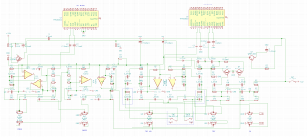
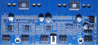
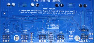
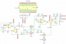
I've spent a bit of time in the last day or two reverse engineering the circuit for this board to see if I could find the source of this high pass but am kinda stumped. I've attached a photo of the board that I took and also the schematic that I've derived from it.
Anyway, from what I can tell, I have put a box around the switch and the components on the board that it is affecting, and I don't see how this would be altering any filters. I'm hoping someone more knowledgable on this sort of thing would be able to shed some light.
Happy to share the Kicad schematic files with anyone if you'd like to see it a bit better. Apologies for the absolutely terrible routing, it is almost literally transposed from the board so the components are mostly in their actual PCB positions.
Cheers!
I have this TPA3116D2 2.1 amp module that I've been messing around with for a while, and one thing I've never been able to figure out the switch on this board that denotes "ALL FREQ <=> NORMAL" which is apparently meant to enable/disable a high-pass filter seems (by my ears) to do nothing.
If you just attach speakers to this and no subwoofer, the L/R outputs seem to produce no lows at all, and if you attach a subwoofer and turn the SUB VOL dial all the way down, it's the same effect regardless of where that switch is located.
I've spent a bit of time in the last day or two reverse engineering the circuit for this board to see if I could find the source of this high pass but am kinda stumped. I've attached a photo of the board that I took and also the schematic that I've derived from it.
Anyway, from what I can tell, I have put a box around the switch and the components on the board that it is affecting, and I don't see how this would be altering any filters. I'm hoping someone more knowledgable on this sort of thing would be able to shed some light.
Happy to share the Kicad schematic files with anyone if you'd like to see it a bit better. Apologies for the absolutely terrible routing, it is almost literally transposed from the board so the components are mostly in their actual PCB positions.
Cheers!
Attachments
Last edited:
You'll need to figure the schematic properly to see the circuit topology. Unfortunately the layout is grid based and thus needlessly obscure. I think its some sort of Baxandall circuit.
I worry that it uses ceramic capacitors where film caps are needed though - if so the
distortion will be high. Normally film caps for a tone circuit are larger than most of those...
I worry that it uses ceramic capacitors where film caps are needed though - if so the
distortion will be high. Normally film caps for a tone circuit are larger than most of those...
You'll need to figure the schematic properly to see the circuit topology. Unfortunately the layout is grid based and thus needlessly obscure.
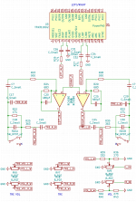
I've spent a bit of time cleaning it up and whittling down to just the input circuitry as much as I think I can, but I had to use global labels as without them (and with my circuit design skill) it was still a complete mess.
As far as I can see, there are two distinct sections; the main "volume" area touching off the VOL, TRE and TRE VOL pots feeding the RC4580 dual opamp, and the VOL, BASS and FREQ pots feeding the pair of TL072 dual opamps.
I wasn't familiar with that, at least in the circuit sense. At a glance it *looks* right, but I can't say. Does this cleaner diagram help with that assessment?I think its some sort of Baxandall circuit.
Thanks for taking a look, at any rate
Attachments
i think i have a similar amp board but just a subwoofer amp. had the same question about the "norm" switch. thanks for your efforts in working it out!
Have you tried hooking it up to some woofers and measuring it while running a frequency sweep? I use it with a pair of full rangers and i have measured a difference, they dont get very low so its really minimal. I can measure again if you want and attach the graphs. Maybe even hook it up to a sub and see if it makes a difference in the very low bass.
Moreover. In the amps page in parts express. There is a pdf file where it states that "6. High Pass Switch: Turns on/off a 6 dB/octave high pass at 150 Hz on the stereo outputs (towards the edge of the board for on)". This is the only place in the internet where i have found this statement on the description of this specific board so i guess parts express maybe conduct their own testing. If you have the tools you should hook it on a oscilloscope and a load and check the frequency response yourself. A lot of people say it just applies a high pass on the satellites no mater where you place the switch
as a side note do you know where the 0db position on the tone control switch is? definitely not at the middle, but the far left doesn't sound right either.
Last edited:
I don't have a scope or anything easily able to measure frequencies etc, my testing so far has been a pair of identical full-range woofers in identical enclosures, one hooked up to either the L or R output, and one to the SUB output. Together, they make a nice full range sound, but if you remove either by either disconnecting, or turning the relevant amp chip volume down, you can hear a clear delineation in the frequencies provided.
The speaker is more than capable of providing frequencies for the SUB output, but when it's being driven in the L/R outputs, it is completely void of low frequencies, qed there must be some kind of high pass on the L/R side. Changing the ALL FREQ/NORM switch back and forth doesn't appear to make any difference to this sound.
Anyway, this is where my expertise and available tools runs out, hence asking for any assistance available here 🙂