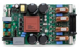
Intrigued by the LITEMOD 4HC design.
4 x 700 W @ 4 ohm
Appears to use only 2 x IRFH5020 mosfets per channel, PQFN 5X6 mm packs!
These are very capable devices: 200V, 43A, 55mOhm, but probably the most interesting feature is the body diode reverse recovery speed of trr = 45 nS!!
I would guess that there is a thick aluminium plate underneath the pcb (just under the fets) linking this to the back plate for thermal transfer, using vias in the PQFN 5X6 decal to link upper side with lower side.
Don't seem to use either snubber, flyback or series diodes. The lack of the diodes is of course because of the very high speed of the body diode.
Thinking of using IRFH5020 for my next project")
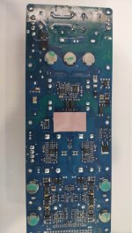
Does anyone have a picture of the underside of the board??
A service manual or schematic would of course also do
/Baldin
4 x 700 W @ 4 ohm
Appears to use only 2 x IRFH5020 mosfets per channel, PQFN 5X6 mm packs!
These are very capable devices: 200V, 43A, 55mOhm, but probably the most interesting feature is the body diode reverse recovery speed of trr = 45 nS!!
I would guess that there is a thick aluminium plate underneath the pcb (just under the fets) linking this to the back plate for thermal transfer, using vias in the PQFN 5X6 decal to link upper side with lower side.
Don't seem to use either snubber, flyback or series diodes. The lack of the diodes is of course because of the very high speed of the body diode.
Thinking of using IRFH5020 for my next project
Does anyone have a picture of the underside of the board??
A service manual or schematic would of course also do
/Baldin
Attachments
I have not seen it personally but I have been told these "copper cylinders" extend to the heatsink, and contact the heatsink through thick silpads. This approach is used by Icepower too. Thermal resistance and thermal cycling is far higher than with a TO-220 pressed to the heatsink through 1mm silpad, about 3-10 times higher. Regarding snubbers Powersoft like Pascal are dirty, ringing in power supply rails is tolerated. Their customers won't look at that. You can try to estimate how all those 100nF ceramic caps will resonate with the electrolytics without intermediate damping electrolytics. Few Mhz few volts amplitude ringing on supply rails on each high current switching event (verified). I do see something looking like RC snubbers on switching nodes, for the >100Mhz ringing resulting from these tiny packages, as the inductance of PCB tracks and series 100nF rail capacitors is still present, note a 4 to 1 reduction in total inductance just shifts ringing 2 times upwards in frequency. No THD or frequency response plots given in Powersoft datasheets. Dirty crosstalk in Pascal at moderate volume like 10-20W (verified). Intended for disco party speakers, as presented by CEOs to designers as project requirements and constraints. Then sold to hi-fi enthusiasts.
Then there are the deceive-the-naive-investor schemes used by IR.
Lets check IRFB4127 datasheet.
- Qrr at 29A, 500A/us, 25C is ~1100nC.
- Qrr at 44A, 500A/us, 25C is ~1350nC.
- 1350 * sqrt (29/44) is 1100nC - It follows a square root law.
IRFB5020 at 7.5A, 500A/us, 25C is rated 460nC.
1350 * sqrt (7.5/44) is 557nC. 17% worse than IRFB5020.
But lets compare Rds-on and power rating at T-case=25C:
- IRFB5020: 8.3W, 0.055r
- IRFB4127: 275W, 0.017r
Oh, wait, but 0.017r can do ~3 times more current without substantial body diode charge storage, provided dead time is optimized.
So in practice nothing in silicon beats a pair of IRFB4127. And IRFB4227 is a bit higher Rds-on, a bit lower Qrr.
It all can be just tacked to company CEOs instructing designers to irrationally shave pennies in assembly cost. But the result is trinket, kickknack (or anyone can give me a better English translation for "baratija" in Spanish?)
(In fact I can say that I had the same fight at Speakerpower Inc, as the company manager visited Audio Trade Fairs ant got seduced by managers from the usual suspect companies. I lost my job rather than making "baratijas". Unlike theirs, my roots can be traced to Marshall Leach, Pass, etc. Bullet proof old-school linear amplifiers that would rot the wires in case of a short at binding posts.)
Last edited:
Hi Eva
Thanks for, as always, an in depth answer
It sure also looks too good that such a small device can provide 700W.
My working horses has so far been IRFB5620 and IRFB4227. IRFB4227 does however require quite some gate current (gate buffers) to work properly .... which is not that big a deal with components like ZXGD3003E6.
I'll keep designing with IRFB4227/IRFB4127 for higher power
While we're at it; another question:
For really high power and high reliability you would go for the full setup with series schottky diodes and large fast flyback diodes. But I've seen examples of using IRFB4227 with a small flyback diode like ES1D or MURS160. This for sure helps reduce (not eliminate) ringing. Dut I would guess they would blow at higher loads.
For it to work, Vf of course needs to be lower than Vf for the body diode, in all working cases (that is why you use a series diode to introduce a voltage drop to ensure the Vf of the flyback diode is always lower). Vf for larger diodes are mostly as high or higher than the body diode, and I guess this is where a small diode like a ES1D comes into play.
Comment?
Best regards Baldin
Powersoft power ratings are tentative, in a sunny day with wind in proper direction.
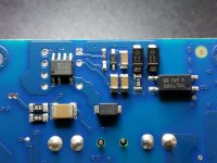
Regarding the underside of the module and related circuits, PSU probably uses UCC2893 in an active clamp flyback approach (as Pascal SPRO)
https://e2e.ti.com/cfs-file/__key/c...s-weblogfiles/00-00-00-03-59/2746.figure1.JPG
And the channels probably use a MC33079 and its lag as a crucial part of self oscillation timing, rather than proper RLC timing circuits,, and IRS20957 input as comparator with unknown performance, unknown hysteresis, unknown glitch immnunity, rather than fast squaring. Same as Pascal SPRO. Never "right hand" validated. Or is it clocked?
The SMD diode in parallel with body diode of TO-220 or TO-247 device just provides a lower inductance path to clamp ringing transient. If the diode is soft enough it reduces snubber requirements considerably, and reduces EMI too with proper low L layout. Plus it protects the driver in case the MOSFET gets open, source or drain bonding wire blown. The series schottky is a different story, maybe that is what SiC or GaN is for? In 200V tech there are lower Qg options like IPP320N20N3 but this comes at the expense of giving up some Rds-on and Qrr.
Last edited:
But as a speaker designer I know that even the bigger Precision Devices, B&C Audio, and similar run out of Xmax, even in tapped horns, with BTL 200V tech. Psoft even made drivers with a different motor scheme, and huge heavy plastic cones starting to break up above 100Hz, in order to sell the higher voltage amplifiers they previously developed. Too many crossover phase/location jumps.
But as a SMPS designer I know that affordable medim speed IGBT can pass a hell load of current efficiently, even at 1200V, provided they can be loaded with a LC tank for zero current turn off.
But as a SMPS designer I know that affordable medim speed IGBT can pass a hell load of current efficiently, even at 1200V, provided they can be loaded with a LC tank for zero current turn off.
Last edited:
Hi Eva
Thanks
So with regards to a parallel smal flyback diode. What would you say the requirements are? Or what would suffice for say IRFB4227 half bridge, on +-80Vdc?
I have a pcb running here at my desk with IRFB4227 but only +-45V, and using ES1D. Reduces the ringing quite some.
ES3D is a little slower, but also handles 3A, and with an SMD package can be implemented in a low L layout.
For proper design I would include a snubber as well.
Would the diode load be the same at steady state (switching, low load) as in high load?
I think the problem is to really know what kind of current spikes will run in the diode. Not that easy to measure. Not that easy to simulate (not sure the component models are that trustworthy).
On the other hand if it fails due to current, it would probably/normally fail open circuit, leading to more HF noise, and ultimately failure of the snubber (as it will have a higher load), again leading to HF noise. So not catastrophic .... but I would rather design for it to work solidly for many years (and not burn my house)
Have tried IPP320N20N3, but either it requires a better pcb design, bigger snubber or a small ferrite bead at the gate, to tame the ringing. I have given it a bit of a rest for the time being as it will require pcb updates to properly experiment with.
Hi Eva
Thanks
So with regards to a parallel smal flyback diode. What would you say the requirements are? Or what would suffice for say IRFB4227 half bridge, on +-80Vdc?
I have a pcb running here at my desk with IRFB4227 but only +-45V, and using ES1D. Reduces the ringing quite some.
ES3D is a little slower, but also handles 3A, and with an SMD package can be implemented in a low L layout.
For proper design I would include a snubber as well.
Would the diode load be the same at steady state (switching, low load) as in high load?
I think the problem is to really know what kind of current spikes will run in the diode. Not that easy to measure. Not that easy to simulate (not sure the component models are that trustworthy).
On the other hand if it fails due to current, it would probably/normally fail open circuit, leading to more HF noise, and ultimately failure of the snubber (as it will have a higher load), again leading to HF noise. So not catastrophic .... but I would rather design for it to work solidly for many years (and not burn my house)
Have tried IPP320N20N3, but either it requires a better pcb design, bigger snubber or a small ferrite bead at the gate, to tame the ringing. I have given it a bit of a rest for the time being as it will require pcb updates to properly experiment with.
The diode has to conduct a low enough % of body diode current (worst case) to avoid overheating. The transients are from dozen nH inductance and are not going to damage the diode. Such diodes fail shorted, unless current is enough to blow the bonding structure of the package. I have used SMB rather than SMA, S320/MBRS320, without problems.
I have not tried IPP320N20N3 but feedback from you and others suggest it is a challenge to try. Will my layout be good enough? haha
Concerning SiC, GaN, IGBT, and LC tanks, the problem they have (hilarious) is that the investors of IGBT and LC tank parts companies are the same as the ones for new semiconductor tech companies. Branches of companies competing between them, actually. Nothing to fear about projecting straight silicon into the future.
Last edited:
Hey Eva, regarding noise on the power supply caused by switching events I have had good success in the past designing the decoupling such that high impedance from the power delivery network is placed between the frequencies excited by the switching frequency and the frequencies excited by the edge rate. Using simple rules of thumb and existing measurements of the PCB and capacitors involved resulted in SPICE simulations that where close to the actual measured power delivery network impedance.
One trick I have had to use before to slow down parts in high dv/dt circuits is adding additional Cgs. Adding gate resistance causes parts to have unintentional turn on due to the Cgd. I had to do this for SiC modules.
One trick I have had to use before to slow down parts in high dv/dt circuits is adding additional Cgs. Adding gate resistance causes parts to have unintentional turn on due to the Cgd. I had to do this for SiC modules.
he he I'm quite sure you can make a better PCB ......... I also just do this as a hobby
Ok, I'll go for a SMB package, and make room for both this and proper snubber.
Don't have any experience with IGBTs, but GaN is a promise which has not really materialised into reality yet. Let's see how it works out in the future
Thanks
Baldin
......... I also just do this as a hobby Ok, I'll go for a SMB package, and make room for both this and proper snubber.
Don't have any experience with IGBTs, but GaN is a promise which has not really materialised into reality yet. Let's see how it works out in the future
Thanks
Baldin
Hi Kipman725:
Problem with ringing on supply rails and self oscillating modulators is that the ringing appears ultra attenuated, but appears, at the output, thus quantizing swtiching timing. Not good for hi-fi. Same problem with clocked modulators, but the triangle is effectively staggered instead.
Baldin:
A 75A medium speed IGBT with built-in diode, for example IKW75N65ES5, priced ~$4/100 units, does 300A pulsed, 80A continuous at Tc=100C, 2.15V drop for 150A at 100C, this is like 0.014r without switching loss as long as the load can be a LC tank, and condution period can be customized to LC tank. Induction heating is the trivial case.
Don't have any experience with IGBTs, but GaN is a promise which has not really materialised into reality yet. Let's see how it works out in the future
Check out GaN systems stuff:
GaN Systems
have used them at switching frequencies up to 27MHz
In my earlier comment I was referring to a method of having clean rail voltages at the devices, there won't be any interference with downstream modulators, the noise is just not there anymore as the currents are flowing in tiny loops around the power device.
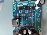
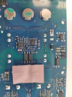
Show some Litemod pictures for you, it's the same design with only 2-ch, they use the copper cylinder to attache the MOSFET(come for NXP) to improve its heat disspation,very smart design.
Attachments
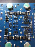
Seems to be using NCP5181 as driver, so maybe the design is different from the 4CH, where it very much looks like there is a IRS20597 or IRS2092 under each output coil .... but I might be mistaken of course .... it would also be a bit strange place to put them ... far from the fets ....
Show some Litemod pictures for you, it's the same design with only 2-ch, they use the copper cylinder to attache the MOSFET(come for NXP) to improve its heat disspation,very smart design.
A couple close pictures of PSU section please?
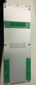
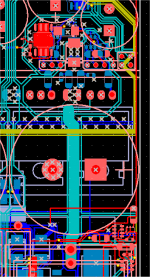
To be honest I'm going to show a trailer of the layout of the project that I was working on when Speakerpower got sold and I got fired. Hidden muscle.
(EDIT: It just requires one or two more manufacuting steps, that can be automated, of course.)
(EDIT: It just requires one or two more manufacuting steps, that can be automated, of course.)
Attachments
Last edited:
- Home
- Amplifiers
- Class D
- Powersoft LITEMOD 4HC .... pic of underside of PCB??