If you just put the +ve and -ve phases of the trafo to the two (+/-) inputs then the CM voltage isn't well defined at AC. Adding the cap provides a low AC CM impedance. Without the cap, it might still work, depending on how well matched the impedances are at the two inputs but I prefer to ensure its going to work.
Also CM rejection of a trafo isn't perfect, the cap to CT helps with that too.
Also CM rejection of a trafo isn't perfect, the cap to CT helps with that too.
I had no idea of using the 3e audio adau1701. The price is cheap and you can study DSP in common with the SY-DAP2002 that you have already purchased. I will consider purchasing. Thank you for your ideas.you can use 3e audio dsp adau1701 which has balanced output and you can take advantage of the dsp and a high performance from analog device IC. Even you can use sigma estudio to enable some filters.
I connected the CT pins of the trafos to GND via an electrolytic cap as the DC potential isn't 0V. I used 2700uF/6.3V
Here's a pic of how I wired up the AVDD caps - bit of a gash job I must admit. There are polymer caps close to the IC (for low ESR) and those bulky Panasonic 15000uFs further away.
woah, looks kind of challenging. How did you manage to solder it the pin17?
I mean why the connection of the middle pin to GND (with or without cap) at all?
i tried disconnecting the middle pin to ground yesterday. Resulted in some squealing and rushing noise. Not very loud but audible from 1m away from my speakers. Putting back the middle pin to ground immediately removed the noise . I did not use any caps like Abraxalito do.
I made my own Y splitter, giving me a female to two female jumper,
connecting the one side to the Pi's BCLK and the other two to the eval board's BCLK and MCLK.
I wonder if this results in a better voltage split to the eval board than the way you jumpered the two?
That seems unlikely to me. Electrically, they should be identical.
Anyway, I just borrowed my wife's ears and she, too, could not here any hiss.
I have the ref board powered by a 12 volt battery.
I just did another test: I thought perhaps the Meanwell switch-mode power supply I'm using was giving off some EMI that the board or jumper cables were picking up. I don't have a 12 volt battery, so I put three 18650 cells in series. They're not fully charged, so I got a little under 12 volts.
With the battery, there is still a hiss, but it is much quieter - quiet enough that it's basically inaudible with the cover on the case. This could be due to the battery vs SMPS, but I suspect it's more to do with the lower voltage (my SMPS is 24V).
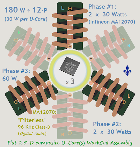
Infineon MA12070 for Flat Magnetics (portable) Induction Heat??
Salutations,
1st of all please displace if/where more suitable!

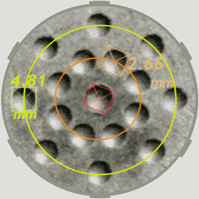
Assuming the goal is to wirelessly "inject" an "energy charge" of ~100 Joules into some flat 17-Holes 0.75 g susceptor within a delay of 2 ~ 3 seconds:

Well so far i've managed to imagine these 2 scenarios:


Would the chip just never start-up or always abort if one ever attempts to try something similar? I wonder.
The concept of Induction Heating ain't exactly new and yet somehow i can't find too much hints relative to generating mainly-convective heat by induction for vaporizer applications potentially supporting precision "Micro-Dosing"... Among possible alloys to test i was thinking of JAi's "PyryFoil" available in 21 Curie temperatures...
Anyway i guess there's no better appropriate board where to ask about the chip being hacked in such brutal manner!
Good day, have fun!!
Salutations,
1st of all please displace if/where more suitable!
Assuming the goal is to wirelessly "inject" an "energy charge" of ~100 Joules into some flat 17-Holes 0.75 g susceptor within a delay of 2 ~ 3 seconds:

The concept of Induction Heating ain't exactly new and yet somehow i can't find too much hints relative to generating mainly-convective heat by induction for vaporizer applications potentially supporting precision "Micro-Dosing"... Among possible alloys to test i was thinking of JAi's "PyryFoil" available in 21 Curie temperatures...
Anyway i guess there's no better appropriate board where to ask about the chip being hacked in such brutal manner!
Good day, have fun!!
Attachments
-
![Heat Decoupling Pads of 12.5 mm dia. x 1 mm Metal Disc with 17 #53 Holes (2019-Jul-31) [400x400].PNG](/community/data/attachments/842/842709-64abd48660640d6b1a6a6086e10ea081.jpg) Heat Decoupling Pads of 12.5 mm dia. x 1 mm Metal Disc with 17 #53 Holes (2019-Jul-31) [400x400].PNG201.1 KB · Views: 1,352
Heat Decoupling Pads of 12.5 mm dia. x 1 mm Metal Disc with 17 #53 Holes (2019-Jul-31) [400x400].PNG201.1 KB · Views: 1,352 -
![Infineon MERUS MA12070 30 Watts x 2 per chip per half of Dual-Band WorkCoil Assembly [300x300] .PNG](/community/data/attachments/842/842712-700d9b3988e350bb704028eb553c6461.jpg) Infineon MERUS MA12070 30 Watts x 2 per chip per half of Dual-Band WorkCoil Assembly [300x300] .PNG352.5 KB · Views: 1,305
Infineon MERUS MA12070 30 Watts x 2 per chip per half of Dual-Band WorkCoil Assembly [300x300] .PNG352.5 KB · Views: 1,305 -
![Egzoset's Concept of a Flat 2.5-D composite U-Core(s) WorkCoil Assembly (2021-Jan-22) [460x480] .PNG](/community/data/attachments/842/842719-4ec38fe6b2077cfdccc91ff1183fa44d.jpg) Egzoset's Concept of a Flat 2.5-D composite U-Core(s) WorkCoil Assembly (2021-Jan-22) [460x480] .PNG864.4 KB · Views: 918
Egzoset's Concept of a Flat 2.5-D composite U-Core(s) WorkCoil Assembly (2021-Jan-22) [460x480] .PNG864.4 KB · Views: 918
Pardon my ignorance, but what exactly are amplifier drivers anyway, and why do I2S amps like the MA12070P need them. Is I2S that non-standard? Is I2C also the issue? I'm currently trying to drive my MA12070P board from an ESP32 board, and am failing miserably. I can modify the MA12070P registers, not that I know which register does what yet, but do drivers do more than access/change registers?
Pardon my ignorance, but what exactly are amplifier drivers anyway, and why do I2S amps like the MA12070P need them. Is I2S that non-standard? Is I2C also the issue? I'm currently trying to drive my MA12070P board from an ESP32 board, and am failing miserably. I can modify the MA12070P registers, not that I know which register does what yet, but do drivers do more than access/change registers?
I'm certainly not an expert, but from my experience, I2S is standardized, though there are a few legitimate yet different types of I2S streams. It seems to me right justified is typical and more common, yet, for whatever reason, the ma12070p defaults to left justified. I2S also has different word sizes, i.e. how many bits make up the smallest unit of data.
On Linux, there is a driver for the ma120x0p amplifier. When I first connected my RPI to my ma12070p reference board, my Linux installation was too old and didn't have that driver. So I configured the RPI for a generic I2S device, which uses right-justified data. In order to get actual playback working, I had to manually use the I2C interface to tell the ma12070p to accept right-justified data.
I am not familiar with the ESP32, but if it can output some fairly reasonable I2S stream, then you should be able to configure the ma12070p to use it. But, I'd wager a nickel that the ESP32 defaults to right-justified, while the ma12070p defaults to left-justified.
I haven't looked at the Linux driver source for the ma120x0p, but I think it's reasonable to assume that it either forces the I2S stream to one the amp recognizes by default, or it uses I2C to set the amp to accept whatever the computer hardware outputs by default. But since the driver also supports volume change, limiter options, etc etc, it's clearly using I2C to communicate with the amp chip.
My suggestion would be to spend a little time getting familiar with the I2C interface. At a minimum, you'll have to make sure the I2S parameters match between the amp chip and the ESP32. But you might also need to un-mute and/or set the volume to non-zero and/or set the limiter to a reasonable value. Before I got the merus-amp driver working on my RPI, I was doing the I2C through Python. I'm happy to share my basic little test code. Even if you don't have Python on the ESP32, I assume there is some programmatic library that has a simple API similar to the Python one I was using. Once you set up the bus for communication, you're literally just reading and writing individual bytes to some address plus an offset. The only real hard part is making sure your bit math is correct, since some functions share an offset. (Ask me how I know!
)If you mean Arduino, Stm32, Esp32, etc by i2c drivers, then yes, they can perform start-up and shut down sequence properly to avoid clicks and noises from ma12070p. So drivers should wakeup amplifier by setting Enable pin from low to high, keeping Mute pin in low while edit registers, and in that stage MCLK with fixed frequency should be present already. If i2s source changed its frequency on the fly, you need to shut down and start-up amplifier with proper sequence again. It's described in ma12070p datasheet (page 30 and 31). BTW those registers may not fit your i2s source format, the default ma12070p i2s mode is left justified, which will cause very loud clicks if your source isn't in that mode. So all that registers changes should be done only while Mute pin is set low by driver. Also I noticed that registers should be changed with delay in 50 milliseconds at least after Enable set to high, otherwise amp will not catch i2c commands, it need that time to stabilize PVDD and BFF before get any commands.Pardon my ignorance, but what exactly are amplifier drivers anyway, and why do I2S amps like the MA12070P need them. Is I2S that non-standard? Is I2C also the issue? I'm currently trying to drive my MA12070P board from an ESP32 board, and am failing miserably. I can modify the MA12070P registers, not that I know which register does what yet, but do drivers do more than access/change registers?
It may take some time to set your amp with trial and error, so it's better to experiment with 4R power resistors connected to the amp instead of speakers that may burned or damaged. It may hurt your ears as well, so be careful with that.
Last edited:
I'm certainly not an expert, but from my experience, I2S is standardized, though there are a few legitimate yet different types of I2S streams. It seems to me right justified is typical and more common, yet, for whatever reason, the ma12070p defaults to left justified. I2S also has different word sizes, i.e. how many bits make up the smallest unit of data.
On Linux, there is a driver for the ma120x0p amplifier. When I first connected my RPI to my ma12070p reference board, my Linux installation was too old and didn't have that driver. So I configured the RPI for a generic I2S device, which uses right-justified data. In order to get actual playback working, I had to manually use the I2C interface to tell the ma12070p to accept right-justified data.
I am not familiar with the ESP32, but if it can output some fairly reasonable I2S stream, then you should be able to configure the ma12070p to use it. But, I'd wager a nickel that the ESP32 defaults to right-justified, while the ma12070p defaults to left-justified.
I haven't looked at the Linux driver source for the ma120x0p, but I think it's reasonable to assume that it either forces the I2S stream to one the amp recognizes by default, or it uses I2C to set the amp to accept whatever the computer hardware outputs by default. But since the driver also supports volume change, limiter options, etc etc, it's clearly using I2C to communicate with the amp chip.
My suggestion would be to spend a little time getting familiar with the I2C interface. At a minimum, you'll have to make sure the I2S parameters match between the amp chip and the ESP32. But you might also need to un-mute and/or set the volume to non-zero and/or set the limiter to a reasonable value. Before I got the merus-amp driver working on my RPI, I was doing the I2C through Python. I'm happy to share my basic little test code. Even if you don't have Python on the ESP32, I assume there is some programmatic library that has a simple API similar to the Python one I was using. Once you set up the bus for communication, you're literally just reading and writing individual bytes to some address plus an offset. The only real hard part is making sure your bit math is correct, since some functions share an offset. (Ask me how I know!
Thanks for the response! I'm a Squeezebox fan, and firmware was developed (Squeezelite-ESP32) to allow this chip to stream from an LMS server to I2S DAC's, but nothing has been written for the Merus amps.
I can "talk" to the amp using I2C, and can access/change registers. And there are a lot of register bits to play with. So far, I get static when I try to play song. Am I right that if I get the right register settings I'm in business, even without a driver?
If you want to set registers via i2c, ma12070p should get MCLK already, in order to work properly, point 5 of start-up sequence in page 30 of datasheetAm I right that if I get the right register settings I'm in business, even without a driver?
If you want to set registers via i2c, ma12070p should get MCLK already, in order to work properly, point 5 of start-up sequence in page 30 of datasheet
I don't have a scope, but I'm pretty sure MCLK is there. Now that I think about it, I believe I can measure the DC voltage between MCLK and GND. If it's 1.65 volts (3.3 volts @ 50% duty cycle) than at least there is something there???
Yes, in this case MCLK exists.I don't have a scope, but I'm pretty sure MCLK is there. Now that I think about it, I believe I can measure the DC voltage between MCLK and GND. If it's 1.65 volts (3.3 volts @ 50% duty cycle) than at least there is something there???
If i2s source changed its frequency on the fly, you need to shut down and start-up amplifier with proper sequence again.
Tried that myself (changing sample rate "on the fly") from 44.1k to 48k and vice versa in order to see what's happening. But ma12070p gets it managed without any audible artefacts.
I forgot to mention again that this ref board has the /ENA pin hard wired to ground and the /MUTE pin to hard wired to VDD. I assume the documented startup procedure isn't really that important. Thanks to everyone for the help. I'll continue to plug away at this since it does sound like I'm on the right track.
One thing I miss is Alsamixer to check the levels. I haven't dealt with so many bits since my IBM assembler days
One thing I miss is Alsamixer to check the levels. I haven't dealt with so many bits since my IBM assembler days
- Home
- Amplifiers
- Class D
- Infineon MA12070 Class D