Hi
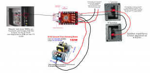
I am trying to build a garden low-cost active speakers so I ordered amplifier board TDA7498e(burned the first), power supply 36v 5A, and Mohr SL10 Speakers connected as the diagram shows below:
So far so good. The thing I don't understand is why the above-mentioned board plays much weaker than a vintage Pioneer SA 508 amp which is rated at 25w per channel at 4Ohms.
Attachments
Hi
I am trying to build a garden low-cost active speakers so I ordered amplifier board TDA7498e(burned the first), power supply 36v 5A, and Mohr SL10 Speakers connected as the diagram shows below:
So far so good. The thing I don't understand is why the above-mentioned board plays much weaker than a vintage Pioneer SA 508 amp which is rated at 25w per channel at 4Ohms.
As Mark says, the sound level you get primarily depends on the gain. The gain in the power amplifier but also in the pre-amplifier and the output level of the source.
A small warning: I have a red TDA7498E board (the same as you show) I have been using with a 31V supply. Recently I got a 36V/7A supply and tried the two together. It played well for a couple of minutes and then the amplifier became silent. No smoke, no noise just became quiet. My conclusion is not to use that board at 36V though it should be able to handle 36V. If you can, adjust the voltage a bit down.
For your circuit diagram I have a few concerns unless you have used jumpers for the board to be in PBTL-mode (mono).
On one channel you have two 4-8 Ohm speakers in parallel which means a resulting speaker impedance down to 2 Ohm. 2 Ohm speakers is only for PBTL-coupling.
The other channel is unloaded which is OK for PBTL-mode but NOT for stereo mode.
Last edited:
No, I haven't. The reason I haven't is that I am a bit worried that I am using 36V supply and I may burn it again.You've tried the different gain adjustment settings?
You've tried the different gain adjustment settings?
Thanks for replying Mark.
To your question. No, I haven't tried different gain setting because I am a bit worried that I may burn it again. The spec sheet got me ordering 36V power supply whereas it seems it runs better with 32V
As Mark says, the sound level you get primarily depends on the gain. The gain in the power amplifier but also in the pre-amplifier and the output level of the source.
A small warning: I have a red TDA7498E board (the same as you show) I have been using with a 31V supply. Recently I got a 36V/7A supply and tried the two together. It played well for a couple of minutes and then the amplifier became silent. No smoke, no noise just became quiet. My conclusion is not to use that board at 36V though it should be able to handle 36V. If you can, adjust the voltage a bit down.
For your circuit diagram, I have a few concerns unless you have used jumpers for the board to be in PBTL-mode (mono).
On one channel you have two 4-8 Ohm speakers in parallel which means a resulting speaker impedance down to 2 Ohm. 2 Ohm speakers is only for PBTL-coupling.
The other channel is unloaded which is OK for PBTL-mode but NOT for stereo mode.
Hi FauxFrench,
My drawing is a bit confusing. I will try to explain the connections I have done.
The amp is inside of the left speaker and the left channel of the amp is going straight to the "crossover"(only 1 capacitor and inductor highpass filter) of the Left speaker which is been desoldered from the terminal plate so I am only using that plate as an extension of the right channel to the right speaker. So eventually you get left channel ->left speaker, right channel -> right speaker
As far as the input signal of the Tv preamplifier, what I've done is play a 1Khz tone on youtube and adjusted the volume until multimeter shows 1V which corresponds to 41% volume on the TV scale.
What would you recommend:
1. Buy a 32V power supply and use the existing amp board.
2. Or use different amp board (witch) with power supply.
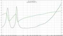
Please note that someone had tested the speakers and they go as low as 3.3-3.5 Ohm most of the time.
Thanks for trying to help
Attachments
My drawing is a bit confusing. I will try to explain the connections I have done.
The amp is inside of the left speaker and the left channel of the amp is going straight to the "crossover"(only 1 capacitor and inductor highpass filter) of the Left speaker which is been desoldered from the terminal plate so I am only using that plate as an extension of the right channel to the right speaker. So eventually you get left channel ->left speaker, right channel -> right speaker
OK, left amplifier channel is to the left speaker and right amplifier channel is to the right speaker? For a class D amplifier, the speaker serves to dampen the output filter resonance and should be permanently connected. Speakers on all outputs!
As far as the input signal of the Tv preamplifier, what I've done is play a 1Khz tone on youtube and adjusted the volume until multimeter shows 1V which corresponds to 41% volume on the TV scale.
What would you recommend:
1. Buy a 32V power supply and use the existing amp board.
I have 24V and 36V power supplies similar to the one you show.
I have looked at them with the hope to tell you how to reduce the output voltage to around 32V. Unfortunately, the type of the controller IC has been grind off. However, for one of the ICs (in a 24V supply) they forgot to grind it off. It is a ON-Semiconductor "1200P60" low-power fly-back controller. As the IC is low-power and the board output considerably higher, power transistors have been added to handle higher currents. Without a circuit diagram I cannot tell you how to adjust the output voltage. In principle the board should handle 36V. I just have a bad experience.
2. Or use different amp board (witch) with power supply. Please note that someone had tested the speakers and they go as low as 3.3-3.5 Ohm most of the time.
The amplifier as such is fine. 3-3.5 Ohm is rather low and I will suggest you a 24V power supply instead. Cheap and standard. For the same TDA7498E board.
Hi
additionally to FF statement i want to add that the decoupling caps 12x 470µ/50V are fake...in this thread i was sure that the size is not correct ot have this voltage/or capacity.....https://www.diyaudio.com/forums/class-d/265387-ebay-cheap-tda7498-boards-41.html#post5288369
so it would be better to keep the voltage lower than 35V
chris
то FauxFrench
First of all, I want to thank you for your willingness to help not only me but almost every member of diyaudio (read lots of your posts) and when you said you recommend 24v PSU that's it, I am no longer searching for an alternative solution that would be it. Ordered it already.
So once again thank you very very much...
To chermann
Thanks for your input chermann, it is much appreciated. Since I will be switching PSU to 24V I would think the fake capacitor would be in the safe zone you recommended "lower than 35V"
ventzitt;5778740[B said:]то FauxFrench
First of all, I want to thank you for your willingness to help not only me but almost every member of diyaudio (read lots of your posts) [/B]...
 ....yes he is really so helpful and a very good engineer....he feels the electrons
Thank you very much to both of you for the kind words.
A comment on "fake" electrolytic capacitors. I am a bad example to other as I buy cheap capacitors from where I am warned. I have only once seen 25V rated capacitors blow-off at 24V with moderate ripple. Only allowing up to 75% of the rated voltage, I have never seen any other capacitors self-destroy. I actually build a capacitance tester for testing all my bigger decoupling capacitors (quite a lot - old, new "fake", reused items, quality brand items etc.). All capacitors were within +/-25% of the stated capacitance, most far closer. All passed a half-voltage leakage test, almost all a full voltage test. A few (possibly fake) I considered should be rated 10%-20% below the actual voltage rating though the original specs are very wide for leakage current. The eldest capacitor was a 2x13000uF picked-out from a 50 year old Marantz 1050D. It passed all tests.
Your 470uF/50V Sanyo capacitors (2x6) will do fine even at 40V. Is there no downsides from "fake" capacitors? Yes - probably on long term life (reliability) and ESR. Thus, less (indirect) performance but no "destroying the gear".
My conclusions:
NEVER use components where you do not know their origin and performance if you take money for your services. Your reputation cannot stand a major mishap.
If you want top-performance from your own gear, buy original components so you have the best performance.
If you are mainly interested in electronic circuit experiments (like I am) you can also use "fake" capacitors though the lifetime may be shorter and the performance somewhat less. If it works with "fake" components, it almost certainly works with genuine components as well.
Recover (salvage) components of reasonable value from any old amplifier/receiver. One day a weirdo, like me, on the forum suggests you to try a component you don't have for overcoming a problem. Then, you dive into your box with recovered components and find something like what is needed. If it works, you can order better for replacement. Else, we spend too much time waiting for components to arrive.
NB: In particular old transformers were often of excellent quality.
@ Faux french
I love to read your posts, you gave me some very good ideas about class D amps and trouble shooting them. Thank you for your patience and keep up the good work. It really helps!
Here is my two cent´s:
I think you guy´s are right, feeling better to use 32 volt with the 7498e instead of the full 36 volts. But there is still good 2 volts margin to the max. operating voltage and some 9 volt to the upper limit of 45 volts. So if nothing goes wrong, this “should” work.
The SMPS of this construction seem to be very reliable, even as they use an IC completely out of spec.at first sight. They are used in a million variety's. The construction may use the IC floating in some way, so the max. voltage of 16 volts is exceeded. I did not find any re commanded application to use it at such high voltage. Most probably a zener diode in the load side, near an opto coupler will set the voltage, but I have not messed with this SMPS so far and would like to leave it alone.
I use the same amplifier and SMPS as the Thread starter. My amp runs without any problem at 36 volt. I used it for preconditioning sub woofer chassis at high load for days and monitored the temperature of all components with an infrared thermometer. There was no part showing more than something near 40°C.
Anyway, I sincerely mistrust any Chinese build quality, components used and quality control. The stuff is too cheap. So IMO you should always take a failing PCB and it´s worst consequences into account. Like a failing SMPS blowing up anything connected to it.
Maybe my personal impression might be of interest for some here.
With this special amp, I have a strong feeling the capacitors in the input are of very bad quality. I compared this board to a very cheap TDA3116 board and while the bass was much stronger, the mid and high range are much worse. This “bass boost” effect somehow disappeared after a few hours,but the much worse “sound” is still audible in the first second of switching amps. As the design of both amps is close to the data sheet, they should sound absolutely comparable.
The "reference" loudspeaker I use for this comparison is a small Tang Band full range in a horn reflex box. I use this inexpensive, small speaker for a very first listening, as it does not have any frequency x-over that might be a disadvantage for an amp and will be only 30€ to replace if an amp blows it. Don´t get me wrong, in no way I´m a "full range fanatic", I prefer "real" speakers, but they give very clear pictures for amp comparison.
Why did´nt I change the suspected electrolytic to some WIMA caps and report about fantastic improvement, you ask?
I have the principle of not modding, as long as I don´t have a second, identical set up for a realistic A-B listening. I have ordered a second amp and SMPS but China sometimes needs a lot of time. Still waiting...
PS even without any additional capacitors in the power supply, the amp plays at medium volume for about 5 seconds before shutting down, if you pull the power plug for the SMPS. There seems to be enough storage, which does not mean that a decent low ESR electrolytic and a few micro Farad of film capacitors could help the sound quality. But as I said, no modding without a second unit for comparison, if possible. So you don´t make a fool of your self, falling for some psycho acoustical effects.
@ Faux french
I love to read your posts, you gave me some very good ideas about class D amps and trouble shooting them. Thank you for your patience and keep up the good work. It really helps!
Here is my two cent´s:
I think you guy´s are right, feeling better to use 32 volt with the 7498e instead of the full 36 volts. But there is still good 2 volts margin to the max. operating voltage and some 9 volt to the upper limit of 45 volts. So if nothing goes wrong, this “should” work.
The SMPS of this construction seem to be very reliable, even as they use an IC completely out of spec.at first sight. They are used in a million variety's. The construction may use the IC floating in some way, so the max. voltage of 16 volts is exceeded. I did not find any re commanded application to use it at such high voltage. Most probably a zener diode in the load side, near an opto coupler will set the voltage, but I have not messed with this SMPS so far and would like to leave it alone.
I use the same amplifier and SMPS as the Thread starter. My amp runs without any problem at 36 volt. I used it for preconditioning sub woofer chassis at high load for days and monitored the temperature of all components with an infrared thermometer. There was no part showing more than something near 40°C.
Anyway, I sincerely mistrust any Chinese build quality, components used and quality control. The stuff is too cheap. So IMO you should always take a failing PCB and it´s worst consequences into account. Like a failing SMPS blowing up anything connected to it.
Thanks!
I chose my TDA7498E board for test of the new 36V power supply because I did not want to use my reworked TPA3255 board. The power supply had been tested with a power resistor for a start but I needed to check how it would work in practice with an amplifier. For some minutes where it played really well without noise or humm, it was a success. Then, the amplifier board stopped and I had to carry-on with the TPA3255 board anyway (also worked well).
I tested (Ohm-meter) the TDA7498E board for short-circuits in the chip output/power and all seem fine. Then, I removed the heatsink and realized that quite some components were hidden underneath. The TDA7498E chip is very small and most of us will not like to change it. A 272 based circuit (probably input buffer), an XL4001 based circuit (voltage regulator) and some more. Something may have stopped working here though the board should operate at 36V. One day I will have to draw-up the schematic to be able to find the defect and I will post the schematic on this forum.
Like you, I am aware that playing around with such cheap electronics will leave faults. For Eastern electronics there are designers, producers and traders but the communication between the three groups may be very sparse. As we know, Chris found out (among other) that the voltage regulator on the TPA3255 board is a 40V version though the seller promises 50V supply. Lack of communication. Could a similar communication mistake have happened for the TDA7498E board? At least yours work at 36V. I will check mine one day.
The 36V power supply I tested is a 220W “big brother” (or sister?) of the 180W board shown. A somewhat bigger transformer, an epoxy-coated control-module but else clearly from the same family. It apparently works well even with 10000uF at the output.
The 45V for the TDA7498E is "Absolute Maximum Ratings" (operational/non-operational?). Recommended operational voltage is maximum 39V. Anyway, you are right that there is a voltage margin.
The 24V supply I suggested for 3-3.5 Ohm speakers is due to peak currents of about 8 amp. The datasheet promises current limits of 11A (typ.) but the TDA7498E is known to be at risk when taken to the limit. Therefore, I suggested to use a 24V standard supply.
Maybe my personal impression might be of interest for some here.
With this special amp, I have a strong feeling the capacitors in the input are of very bad quality. I compared this board to a very cheap TDA3116 board and while the bass was much stronger, the mid and high range are much worse. This “bass boost” effect somehow disappeared after a few hours,but the much worse “sound” is still audible in the first second of switching amps. As the design of both amps is close to the data sheet, they should sound absolutely comparable.
The "reference" loudspeaker I use for this comparison is a small Tang Band full range in a horn reflex box. I use this inexpensive, small speaker for a very first listening, as it does not have any frequency x-over that might be a disadvantage for an amp and will be only 30€ to replace if an amp blows it. Don´t get me wrong, in no way I´m a "full range fanatic", I prefer "real" speakers, but they give very clear pictures for amp comparison.
Why did´nt I change the suspected electrolytic to some WIMA caps and report about fantastic improvement, you ask?
I have the principle of not modding, as long as I don´t have a second, identical set up for a realistic A-B listening. I have ordered a second amp and SMPS but China sometimes needs a lot of time. Still waiting...
PS even without any additional capacitors in the power supply, the amp plays at medium volume for about 5 seconds before shutting down, if you pull the power plug for the SMPS. There seems to be enough storage, which does not mean that a decent low ESR electrolytic and a few micro Farad of film capacitors could help the sound quality. But as I said, no modding without a second unit for comparison, if possible. So you don´t make a fool of your self, falling for some psycho acoustical effects.
1uF foil capacitors used as coupling capacitors at the input. Same type 220nF/470nF foil capacitors used in the output filter. I never suspected those but I will give them consideration when the board works again.
Even if we have identical looking boards, they may be not the same. I have amps where I ordered more than once (because import tax limit) and they look exactly the same on first sight. Later I realised they where different in some details. Maybe made by two factory´s copying the same copy...
This is why I am very carefull about giving others advice. If you burn the second board without probable cause, it might be the voltage. Maybe your board would have been blowing up with 24 volt as well, just an hour later?
Believe me, no Chinaman changes anything on a board that runs on 90% of the voltage it is made for. It is not that he has sinister ideas about finacially harming the stupid long nose, he send´s it to, he just has no clue what he has been copying and what all the parts are there for. Surprising how big a brand can become, if they only choose the colour for their junk. Hello Sure, Iam sure not talking about Wondom...
- Status
- This old topic is closed. If you want to reopen this topic, contact a moderator using the "Report Post" button.
- Home
- Amplifiers
- Class D
- TDA7498e + Mohr SL10