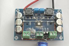
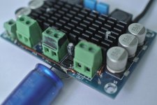
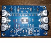
This thread concerns methmorphosing a TPA3116 PBTL mono (2.78$) module into highest audiophile level amplifier, surpassing the reference 300B SE 5hz-100khz amplifier.
sublimed TPA3116. / 300B
[URL="http://www.youtube.com/watch?v=wFaL2Xne38s"]www.youtube.com/watch?v=wFaL2Xne[/URL]38s. www.youtube.com/watch?v=JE8UCIlIYVA
www.youtube.com/watch?v=6lB4oRgCMeA. www.youtube.com/watch?v=KsWupRryrpM
www.youtube.com/watch?v=n5zWg72VUfM. www.youtube.com/watch?v=h_q8OgJ-pG0
www.youtube.com/watch?v=4dCttlb55kI. www.youtube.com/watch?v=RN-WVlK5awk
recorded with Takstar cm60 undirectional microphone without AGC. Recorder NikonV1 . The speaker is described on Fullrange forum .corner Chambord with passive radiating sphere
To audiophilize this rough amplifier , five aspects of modifications are necessary .
First is of electrical nature. It must comply with American wire gauge recommendation .
Second, to ground the thermal pad by the heatsink as recommended by the datasheet for best performance . With ohm meter the pad is not linked to anything , but the midrange sound strangled without grounding . Probably grounding the substrate cancels capacitive parasite links.
Third is to higher the frequency to 1.2Mhz , which is the only reason why I got back interested in class D .
Fouth is to minimize the problem due to hysteresis of the comparators . This is the most engineering part.
Fifth is to resolve start up and shut down plop problem .
https://www.powerstream.com/Wire_Size.
The American wire gauge is scrupulously respected by electricians , whether high voltage power transmission , transformer winding ,capacitor leads etc. For electronicians , doubtless about their instructed knowledge , describe according to their simplified understanding that max. current vs thickness , a mater of resistance, even by a Dr ès Science on a forum where also a PhD explaining the higher current in chassis to be cooling effect .
Breguet , a watch maker who was commissioned to produce precision parts for telegraph line transmission , realized that 0.1mm wire gets distroyed at 3A whatever is the length . He created by this a sacrificial wire to be destroyed and protect the long higher resistance telegraph cable from lightning strike. Edison , 30 years after inventing the electric lamp which he acquired good understanding about wires, patented the fuse . Who found out the nonlinear character is due to the magnetic field caused by the current passing through, I don't know , but constraining the field nearer to the wire by a steal chassis or the wire itself made of magnetic alloy , increases substantially the linearity of the wire. Once upon a time transistors in metal cases had all magnetic leads as most capacitors have , whereas nowadays as TPA3116 has hair thickness nonmagnetic leads to pass 7A, let's not talk about pc boards . All current carrying tracks need to be enforced by electrolytic capacitor leads , or thick wires, the IC is to be covered by a transformer laminate steal as a pad between the heatsink , the under side of the IC is also to be covered by a large or multiple steal plate . The outputs are harvested directly from the inductors , and the output screw outlets are transformed into +24v .The +Vcc is joint to the -Vcc to form both screws recieve the 0v ground . The two diodes cathodes are linked to the new +24 . By this Vcc+&- becomes 0v and out+&- becomes +24v .
The output pcb tracks linking the inductors to the screw outlets are to be canceled by cutting them both at departure (upper)edge and arrival (lower edge) . You need to drill two holes of 1mm , one near external side, uppon cut track, and another uppon + of front side . Another screw single outlet is installed for signal ground , and another on the opposite side will be installed to link R6 for Mute function . An electrolytic capacitor of 6800uf/35v for 8 ohm ,soldered between 24v and ground. Two 1mm wires bring the 24v on each bank , thick capacitor leads continue to the IC +V supplies linking also the decoupling capacitors. The inductors are linked by thick magnetic leads to the junction of two capacitors . A second thick lead links to the juntion of the two outputs , a third thinner lead in form of U links the output feet of the IC to the second lead after destroy the ground extension of the pins between the output pins for ease of soldering ( this last U leads took ½ hour) .
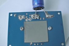
The Heathsink
The heathsink is glued by soft silicon . To release the heathsink push upon it on the connectors side about few hundred gram force . The hight of the IC profile is lower than the capacitors , the thickness of the steal pad that you will add will be just enough. You nead to drill and filet two holes for two 2mm screws . These screws will bring the electric potential . The pad is cleared from isolator as well as the heatsink only under one edge of the pad . The size of the pad must large but not reaching the side capacitors and wide to cover the tracks of power side . Glue sparsely with silicon or universal glue and move the pad back and forth to form thinnest glue . With a sharp scalpel clean on the nonisolated edge the glue between the two metals and apply solder . Of course the metals will refuse, but the melted solder will enter between the metals and provide electric conductance that you will verify . To install the heatsink is an art . First you must verify that the under components ,wires are lower than heatsink by inclining it four sides , hold the heatsink with thumb and index flat on the IC and install on screw until it just pulls it to incline . Install tha second screw but tighter slightly to tighten both gradualy and alternately .
The frequency
You need to replace the 33uh(330) inductors with 10uh(100) ones , their capacitor 680nf to 220nf for 8 ohms load . The AM2 grounded pin must (4th front right) must be liberated . Holding the circuit the inductors to your side apply a scalpel vertically between 4&5 pin so that when you rotate the scalpel it forces the pin 4 outwards . With the sodering iron heating the pin 2 ,3&4 the 4th goes out but obliquely . Once the exceeding solder is pumped out the pin remains alone to be carefully realined . You need a 10k-100k smd resistor (1/8 resistor my choice is very very bad ) to solder one edge on 24v along with R1 solder the other edge a thin isolated wire ,determine the length and scrap off the isolator only the upper part . With a piece of paper under the pin , slide the wire under the pin and solder it. Replace the paper with a wide adhesive tape and cover the pin with a small one . Push the pin to be lower than the IC .
The hysteresis ,aiy yai yai !
May be all class D amps do need to pass the analog signal through a comparator . Comparators have a hysteresis voltage that the signal needs to overcome to invert back the output . The error signal when reaches the comparator, the high frequency errors are smashed by integrator, to get erased by the hysteresis . This results a sound much cleaner that the original as the very small variation that makes a sound to be that of multiple same instruments or voices get erased . If it was an image it would look like cartoon style with clearly defined outlines, plain colors . Most probably class D lovers call this liquid midrange sound . Now ,I would like to have such a processor in a preamplfier, but not in the output . If you listen Mozard's Requiem , very very rare amplifiers can reproduce this music that I atribute 5 stars .https://www.youtube.com/watch?v=S_e7K7io92g Listen to it before modifying , you will be amazed by the cleanness . When you switch to jazz music of large orchestral music as Benny Goodman's sing sing sing , the beat of 28 horn instruments is gone and the orchestra sounds to be a few instruments . The trouble arises when you are dealing with symphonic orchestras , the instruments get mixed up, provoking heavy ear whistling acompanied with headache ending up at a TV sound level . To relish my bleeding ears I switched to simpler music and stonished I stumbled on one that normally passes without any problem with any amplifier https://www.youtube.com/watch?v=H5kDfJMutuY but with this amp it is unlistenable . I used it as reference music to tune this amplifier .
To surpass the hysteresis, the remedy is to apply the maximum possible negative feedback ratio to make the error signal highest.
This amp is wired in single input mode , but with the potentiometer at maximum, have an unacceptable noise . This means only differential input is possible . By applying a 600/10k input transformer and a stereo potentiometer to provide adjustable input impedance , the reference music sounded good with 270k and above . This amplifier is adjusted for maximum gain with feedback resistors of 300k and input 4.5k . This means the maximum gain this amplifier can be used for excellent sounding (for my ears) is unity . With 600/10k ,2Vrms can deliver only 8 watts .
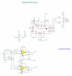
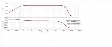
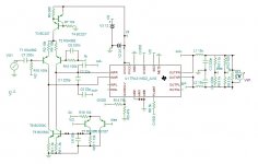
To make it better, I switched to active input adapter , a high impedance 1M ohm holloway or biphase current amplifier . The inputs of TPA13116 are at 3v , this requires low voltage op amp the OPA2365 . The circuit initialy had a non decoupled power supply , as the two opamps function in differential mode hence constant power supply current . The sound was incredibly dynamic , never heard such ever before , but the bass was weak with distorted orchestral explosions . Adding an ordinary 100uf , this time the dynamic flattened but I heard totally new sound of drums in Beethoven's 3rd . I added an inductor and 1000uf decoupling capacitor upon 24v , replaced the ordinary 100uf with low esr 150uf and seperated the signal ground from the supply . Yes, I could get most of the dynamic back , but there is still more under the hood to be released . I added an all pass filter to linearize the phase responce, so that the fix delay of the clock and the variable of the analog part match ,to form a linearly varying phase responce (see the graph ). You can hear how high frequency instruments sound so natural .
If the main board is finished ,the auxiliary input circuit needs still more engineering , after all, I worked on this project only 10 days, 2-3 hours a day whereas it requires several weeks to tune an amp .
The potentiometer and the two input capacitors need to be taken off . on the bottom side enlarge the ground surrounding the input endings as well the input terminals after isolating the -input from the ground . This points are of high impedance , and 1M ohm leak to ground due to solder flux ,results loss in feedback error signal by 50%. Link the input terminals to input endings with thin isolated wire.
Start up/shut down plop .
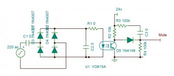
The amplifier shuts down with an unacceptable plop for an audiophilized amplfier . And on start up if with an input transformer is total silence ,it is not the case with differential current amplifier . To mute both plops and stop the amplifier instantly on off , I will add an external circuit . The opto coupler is active by the mains AC . On start the capacitor charge time keeps the mute active , while on off , the diode conducts and mutes the amp instantly holding the mute voltage at 90% of the decaying supply.
4ohms version needs 10uh inductors to be paralleld upon by another 10uh , the capacitors pass 220nf to 390nf , the 24v decoupling capacitor pass to 15000uf the power supply pass from 4A to 10A. I did not tried it and I will not , these are the values given by the simulator.
Warning: If you are using high voltage soldering iron , you must unplug every time you will use , 60W is best choice .
https://www.aliexpress.com/item/XH-M542-TPA3116-D2-single-channel-high-power-digital-audio-power-amplifier-board-TPA3116D2-mobile-speaker/32980226449.html?spm=a2g0s.9042311.0.0.ce914c4dYLiOWV
sublimed TPA3116. / 300B
[URL="http://www.youtube.com/watch?v=wFaL2Xne38s"]www.youtube.com/watch?v=wFaL2Xne[/URL]38s. www.youtube.com/watch?v=JE8UCIlIYVA
www.youtube.com/watch?v=6lB4oRgCMeA. www.youtube.com/watch?v=KsWupRryrpM
www.youtube.com/watch?v=n5zWg72VUfM. www.youtube.com/watch?v=h_q8OgJ-pG0
www.youtube.com/watch?v=4dCttlb55kI. www.youtube.com/watch?v=RN-WVlK5awk
recorded with Takstar cm60 undirectional microphone without AGC. Recorder NikonV1 . The speaker is described on Fullrange forum .corner Chambord with passive radiating sphere
To audiophilize this rough amplifier , five aspects of modifications are necessary .
First is of electrical nature. It must comply with American wire gauge recommendation .
Second, to ground the thermal pad by the heatsink as recommended by the datasheet for best performance . With ohm meter the pad is not linked to anything , but the midrange sound strangled without grounding . Probably grounding the substrate cancels capacitive parasite links.
Third is to higher the frequency to 1.2Mhz , which is the only reason why I got back interested in class D .
Fouth is to minimize the problem due to hysteresis of the comparators . This is the most engineering part.
Fifth is to resolve start up and shut down plop problem .
https://www.powerstream.com/Wire_Size.
The American wire gauge is scrupulously respected by electricians , whether high voltage power transmission , transformer winding ,capacitor leads etc. For electronicians , doubtless about their instructed knowledge , describe according to their simplified understanding that max. current vs thickness , a mater of resistance, even by a Dr ès Science on a forum where also a PhD explaining the higher current in chassis to be cooling effect .
Breguet , a watch maker who was commissioned to produce precision parts for telegraph line transmission , realized that 0.1mm wire gets distroyed at 3A whatever is the length . He created by this a sacrificial wire to be destroyed and protect the long higher resistance telegraph cable from lightning strike. Edison , 30 years after inventing the electric lamp which he acquired good understanding about wires, patented the fuse . Who found out the nonlinear character is due to the magnetic field caused by the current passing through, I don't know , but constraining the field nearer to the wire by a steal chassis or the wire itself made of magnetic alloy , increases substantially the linearity of the wire. Once upon a time transistors in metal cases had all magnetic leads as most capacitors have , whereas nowadays as TPA3116 has hair thickness nonmagnetic leads to pass 7A, let's not talk about pc boards . All current carrying tracks need to be enforced by electrolytic capacitor leads , or thick wires, the IC is to be covered by a transformer laminate steal as a pad between the heatsink , the under side of the IC is also to be covered by a large or multiple steal plate . The outputs are harvested directly from the inductors , and the output screw outlets are transformed into +24v .The +Vcc is joint to the -Vcc to form both screws recieve the 0v ground . The two diodes cathodes are linked to the new +24 . By this Vcc+&- becomes 0v and out+&- becomes +24v .
The output pcb tracks linking the inductors to the screw outlets are to be canceled by cutting them both at departure (upper)edge and arrival (lower edge) . You need to drill two holes of 1mm , one near external side, uppon cut track, and another uppon + of front side . Another screw single outlet is installed for signal ground , and another on the opposite side will be installed to link R6 for Mute function . An electrolytic capacitor of 6800uf/35v for 8 ohm ,soldered between 24v and ground. Two 1mm wires bring the 24v on each bank , thick capacitor leads continue to the IC +V supplies linking also the decoupling capacitors. The inductors are linked by thick magnetic leads to the junction of two capacitors . A second thick lead links to the juntion of the two outputs , a third thinner lead in form of U links the output feet of the IC to the second lead after destroy the ground extension of the pins between the output pins for ease of soldering ( this last U leads took ½ hour) .
The Heathsink
The heathsink is glued by soft silicon . To release the heathsink push upon it on the connectors side about few hundred gram force . The hight of the IC profile is lower than the capacitors , the thickness of the steal pad that you will add will be just enough. You nead to drill and filet two holes for two 2mm screws . These screws will bring the electric potential . The pad is cleared from isolator as well as the heatsink only under one edge of the pad . The size of the pad must large but not reaching the side capacitors and wide to cover the tracks of power side . Glue sparsely with silicon or universal glue and move the pad back and forth to form thinnest glue . With a sharp scalpel clean on the nonisolated edge the glue between the two metals and apply solder . Of course the metals will refuse, but the melted solder will enter between the metals and provide electric conductance that you will verify . To install the heatsink is an art . First you must verify that the under components ,wires are lower than heatsink by inclining it four sides , hold the heatsink with thumb and index flat on the IC and install on screw until it just pulls it to incline . Install tha second screw but tighter slightly to tighten both gradualy and alternately .
The frequency
You need to replace the 33uh(330) inductors with 10uh(100) ones , their capacitor 680nf to 220nf for 8 ohms load . The AM2 grounded pin must (4th front right) must be liberated . Holding the circuit the inductors to your side apply a scalpel vertically between 4&5 pin so that when you rotate the scalpel it forces the pin 4 outwards . With the sodering iron heating the pin 2 ,3&4 the 4th goes out but obliquely . Once the exceeding solder is pumped out the pin remains alone to be carefully realined . You need a 10k-100k smd resistor (1/8 resistor my choice is very very bad ) to solder one edge on 24v along with R1 solder the other edge a thin isolated wire ,determine the length and scrap off the isolator only the upper part . With a piece of paper under the pin , slide the wire under the pin and solder it. Replace the paper with a wide adhesive tape and cover the pin with a small one . Push the pin to be lower than the IC .
The hysteresis ,aiy yai yai !
May be all class D amps do need to pass the analog signal through a comparator . Comparators have a hysteresis voltage that the signal needs to overcome to invert back the output . The error signal when reaches the comparator, the high frequency errors are smashed by integrator, to get erased by the hysteresis . This results a sound much cleaner that the original as the very small variation that makes a sound to be that of multiple same instruments or voices get erased . If it was an image it would look like cartoon style with clearly defined outlines, plain colors . Most probably class D lovers call this liquid midrange sound . Now ,I would like to have such a processor in a preamplfier, but not in the output . If you listen Mozard's Requiem , very very rare amplifiers can reproduce this music that I atribute 5 stars .https://www.youtube.com/watch?v=S_e7K7io92g Listen to it before modifying , you will be amazed by the cleanness . When you switch to jazz music of large orchestral music as Benny Goodman's sing sing sing , the beat of 28 horn instruments is gone and the orchestra sounds to be a few instruments . The trouble arises when you are dealing with symphonic orchestras , the instruments get mixed up, provoking heavy ear whistling acompanied with headache ending up at a TV sound level . To relish my bleeding ears I switched to simpler music and stonished I stumbled on one that normally passes without any problem with any amplifier https://www.youtube.com/watch?v=H5kDfJMutuY but with this amp it is unlistenable . I used it as reference music to tune this amplifier .
To surpass the hysteresis, the remedy is to apply the maximum possible negative feedback ratio to make the error signal highest.
This amp is wired in single input mode , but with the potentiometer at maximum, have an unacceptable noise . This means only differential input is possible . By applying a 600/10k input transformer and a stereo potentiometer to provide adjustable input impedance , the reference music sounded good with 270k and above . This amplifier is adjusted for maximum gain with feedback resistors of 300k and input 4.5k . This means the maximum gain this amplifier can be used for excellent sounding (for my ears) is unity . With 600/10k ,2Vrms can deliver only 8 watts .
To make it better, I switched to active input adapter , a high impedance 1M ohm holloway or biphase current amplifier . The inputs of TPA13116 are at 3v , this requires low voltage op amp the OPA2365 . The circuit initialy had a non decoupled power supply , as the two opamps function in differential mode hence constant power supply current . The sound was incredibly dynamic , never heard such ever before , but the bass was weak with distorted orchestral explosions . Adding an ordinary 100uf , this time the dynamic flattened but I heard totally new sound of drums in Beethoven's 3rd . I added an inductor and 1000uf decoupling capacitor upon 24v , replaced the ordinary 100uf with low esr 150uf and seperated the signal ground from the supply . Yes, I could get most of the dynamic back , but there is still more under the hood to be released . I added an all pass filter to linearize the phase responce, so that the fix delay of the clock and the variable of the analog part match ,to form a linearly varying phase responce (see the graph ). You can hear how high frequency instruments sound so natural .
If the main board is finished ,the auxiliary input circuit needs still more engineering , after all, I worked on this project only 10 days, 2-3 hours a day whereas it requires several weeks to tune an amp .
The potentiometer and the two input capacitors need to be taken off . on the bottom side enlarge the ground surrounding the input endings as well the input terminals after isolating the -input from the ground . This points are of high impedance , and 1M ohm leak to ground due to solder flux ,results loss in feedback error signal by 50%. Link the input terminals to input endings with thin isolated wire.
Start up/shut down plop .
The amplifier shuts down with an unacceptable plop for an audiophilized amplfier . And on start up if with an input transformer is total silence ,it is not the case with differential current amplifier . To mute both plops and stop the amplifier instantly on off , I will add an external circuit . The opto coupler is active by the mains AC . On start the capacitor charge time keeps the mute active , while on off , the diode conducts and mutes the amp instantly holding the mute voltage at 90% of the decaying supply.
4ohms version needs 10uh inductors to be paralleld upon by another 10uh , the capacitors pass 220nf to 390nf , the 24v decoupling capacitor pass to 15000uf the power supply pass from 4A to 10A. I did not tried it and I will not , these are the values given by the simulator.
Warning: If you are using high voltage soldering iron , you must unplug every time you will use , 60W is best choice .
https://www.aliexpress.com/item/XH-M542-TPA3116-D2-single-channel-high-power-digital-audio-power-amplifier-board-TPA3116D2-mobile-speaker/32980226449.html?spm=a2g0s.9042311.0.0.ce914c4dYLiOWV
Attachments
Last edited:
You get far better result with mono PBTL . The module costs only 2.78$ inc. Shipment (for me) . I ordered another one to try a different way of modifying . I will drill holes where the pair of outputs join and install the inductors just beneath it . By this only the U s need to be soldered. The 24v same way I will drill holes on either side of the IC and bring with thick wires from under . The two decoupling capacitors on the circuit then be installed under , paralleled by two 3300uf on each side (under) instead of one 6800uf on the socket . To pull up the AM2 , instead of adding a resistor, I will link it to R1 (SDZ FAULT) .interesting! I have a stereo module unused.
This thread concerns methmorphosing a TPA3116 PBTL mono (2.78$) module into highest audiophile level amplifier, surpassing the reference 300B SE 5hz-100khz amplifier.
sublimed TPA3116. / 300B
www.youtube.com/watch?v=wFaL2Xne38s. www.youtube.com/watch?v=JE8UCIlIYVA
www.youtube.com/watch?v=6lB4oRgCMeA. www.youtube.com/watch?v=KsWupRryrpM
www.youtube.com/watch?v=n5zWg72VUfM. www.youtube.com/watch?v=h_q8OgJ-pG0
www.youtube.com/watch?v=4dCttlb55kI. www.youtube.com/watch?v=RN-WVlK5awk
recorded with Takstar cm60 undirectional microphone without AGC. Recorder NikonV1 . The speaker is described on Fullrange forum .corner Chambord with passive radiating sphere
To audiophilize this rough amplifier , five aspects of modifications are necessary .
First is of electrical nature. It must comply with American wire gauge recommendation .
Second, to ground the thermal pad by the heatsink as recommended by the datasheet for best performance . With ohm meter the pad is not linked to anything , but the midrange sound strangled without grounding . Probably grounding the substrate cancels capacitive parasite links.
Third is to higher the frequency to 1.2Mhz , which is the only reason why I got back interested in class D .
Fouth is to minimize the problem due to hysteresis of the comparators . This is the most engineering part.
Fifth is to resolve start up and shut down plop problem .
https://www.powerstream.com/Wire_Size.
The American wire gauge is scrupulously respected by electricians , whether high voltage power transmission , transformer winding ,capacitor leads etc. For electronicians , doubtless about their instructed knowledge , describe according to their simplified understanding that max. current vs thickness , a mater of resistance, even by a Dr ès Science on a forum where also a PhD explaining the higher current in chassis to be cooling effect .
Breguet , a watch maker who was commissioned to produce precision parts for telegraph line transmission , realized that 0.1mm wire gets distroyed at 3A whatever is the length . He created by this a sacrificial wire to be destroyed and protect the long higher resistance telegraph cable from lightning strike. Edison , 30 years after inventing the electric lamp which he acquired good understanding about wires, patented the fuse . Who found out the nonlinear character is due to the magnetic field caused by the current passing through, I don't know , but constraining the field nearer to the wire by a steal chassis or the wire itself made of magnetic alloy , increases substantially the linearity of the wire. Once upon a time transistors in metal cases had all magnetic leads as most capacitors have , whereas nowadays as TPA3116 has hair thickness nonmagnetic leads to pass 7A, let's not talk about pc boards . All current carrying tracks need to be enforced by electrolytic capacitor leads , or thick wires, the IC is to be covered by a transformer laminate steal as a pad between the heatsink , the under side of the IC is also to be covered by a large or multiple steal plate . The outputs are harvested directly from the inductors , and the output screw outlets are transformed into +24v .The +Vcc is joint to the -Vcc to form both screws recieve the 0v ground . The two diodes cathodes are linked to the new +24 . By this Vcc+&- becomes 0v and out+&- becomes +24v .
The output pcb tracks linking the inductors to the screw outlets are to be canceled by cutting them both at departure (upper)edge and arrival (lower edge) . You need to drill two holes of 1mm , one near external side, uppon cut track, and another uppon + of front side . Another screw single outlet is installed for signal ground , and another on the opposite side will be installed to link R6 for Mute function . An electrolytic capacitor of 6800uf/35v for 8 ohm ,soldered between 24v and ground. Two 1mm wires bring the 24v on each bank , thick capacitor leads continue to the IC +V supplies linking also the decoupling capacitors. The inductors are linked by thick magnetic leads to the junction of two capacitors . A second thick lead links to the juntion of the two outputs , a third thinner lead in form of U links the output feet of the IC to the second lead after destroy the ground extension of the pins between the output pins for ease of soldering ( this last U leads took ½ hour) .
The Heathsink
The heathsink is glued by soft silicon . To release the heathsink push upon it on the connectors side about few hundred gram force . The hight of the IC profile is lower than the capacitors , the thickness of the steal pad that you will add will be just enough. You nead to drill and filet two holes for two 2mm screws . These screws will bring the electric potential . The pad is cleared from isolator as well as the heatsink only under one edge of the pad . The size of the pad must large but not reaching the side capacitors and wide to cover the tracks of power side . Glue sparsely with silicon or universal glue and move the pad back and forth to form thinnest glue . With a sharp scalpel clean on the nonisolated edge the glue between the two metals and apply solder . Of course the metals will refuse, but the melted solder will enter between the metals and provide electric conductance that you will verify . To install the heatsink is an art . First you must verify that the under components ,wires are lower than heatsink by inclining it four sides , hold the heatsink with thumb and index flat on the IC and install on screw until it just pulls it to incline . Install tha second screw but tighter slightly to tighten both gradualy and alternately .
The frequency
You need to replace the 33uh(330) inductors with 10uh(100) ones , their capacitor 680nf to 220nf for 8 ohms load . The AM2 grounded pin must (4th front right) must be liberated . Holding the circuit the inductors to your side apply a scalpel vertically between 4&5 pin so that when you rotate the scalpel it forces the pin 4 outwards . With the sodering iron heating the pin 2 ,3&4 the 4th goes out but obliquely . Once the exceeding solder is pumped out the pin remains alone to be carefully realined . You need a 10k-100k smd resistor (1/8 resistor my choice is very very bad ) to solder one edge on 24v along with R1 solder the other edge a thin isolated wire ,determine the length and scrap off the isolator only the upper part . With a piece of paper under the pin , slide the wire under the pin and solder it. Replace the paper with a wide adhesive tape and cover the pin with a small one . Push the pin to be lower than the IC .
The hysteresis ,aiy yai yai !
May be all class D amps do need to pass the analog signal through a comparator . Comparators have a hysteresis voltage that the signal needs to overcome to invert back the output . The error signal when reaches the comparator, the high frequency errors are smashed by integrator, to get erased by the hysteresis . This results a sound much cleaner that the original as the very small variation that makes a sound to be that of multiple same instruments or voices get erased . If it was an image it would look like cartoon style with clearly defined outlines, plain colors . Most probably class D lovers call this liquid midrange sound . Now ,I would like to have such a processor in a preamplfier, but not in the output . If you listen Mozard's Requiem , very very rare amplifiers can reproduce this music that I atribute 5 stars .https://www.youtube.com/watch?v=S_e7K7io92g Listen to it before modifying , you will be amazed by the cleanness . When you switch to jazz music of large orchestral music as Benny Goodman's sing sing sing , the beat of 28 horn instruments is gone and the orchestra sounds to be a few instruments . The trouble arises when you are dealing with symphonic orchestras , the instruments get mixed up, provoking heavy ear whistling acompanied with headache ending up at a TV sound level . To relish my bleeding ears I switched to simpler music and stonished I stumbled on one that normally passes without any problem with any amplifier https://www.youtube.com/watch?v=H5kDfJMutuY but with this amp it is unlistenable . I used it as reference music to tune this amplifier .
To surpass the hysteresis, the remedy is to apply the maximum possible negative feedback ratio to make the error signal highest.
This amp is wired in single input mode , but with the potentiometer at maximum, have an unacceptable noise . This means only differential input is possible . By applying a 600/10k input transformer and a stereo potentiometer to provide adjustable input impedance , the reference music sounded good with 270k and above . This amplifier is adjusted for maximum gain with feedback resistors of 300k and input 4.5k . This means the maximum gain this amplifier can be used for excellent sounding (for my ears) is unity . With 600/10k ,2Vrms can deliver only 8 watts .
To make it better, I switched to active input adapter , a high impedance 1M ohm holloway or biphase current amplifier . The inputs of TPA13116 are at 3v , this requires low voltage op amp the OPA2365 . The circuit initialy had a non decoupled power supply , as the two opamps function in differential mode hence constant power supply current . The sound was incredibly dynamic , never heard such ever before , but the bass was weak with distorted orchestral explosions . Adding an ordinary 100uf , this time the dynamic flattened but I heard totally new sound of drums in Beethoven's 3rd . I added an inductor and 1000uf decoupling capacitor upon 24v , replaced the ordinary 100uf with low esr 150uf and seperated the signal ground from the supply . Yes, I could get most of the dynamic back , but there is still more under the hood to be released . I added an all pass filter to linearize the phase responce, so that the fix delay of the clock and the variable of the analog part match ,to form a linearly varying phase responce (see the graph ). You can hear how high frequency instruments sound so natural .
If the main board is finished ,the auxiliary input circuit needs still more engineering , after all, I worked on this project only 10 days, 2-3 hours a day whereas it requires several weeks to tune an amp .
The potentiometer and the two input capacitors need to be taken off . on the bottom side enlarge the ground surrounding the input endings as well the input terminals after isolating the -input from the ground . This points are of high impedance , and 1M ohm leak to ground due to solder flux ,results loss in feedback error signal by 50%. Link the input terminals to input endings with thin isolated wire.
Start up/shut down plop .
The amplifier shuts down with an unacceptable plop for an audiophilized amplfier . And on start up if with an input transformer is total silence ,it is not the case with differential current amplifier . To mute both plops and stop the amplifier instantly on off , I will add an external circuit . The opto coupler is active by the mains AC . On start the capacitor charge time keeps the mute active , while on off , the diode conducts and mutes the amp instantly holding the mute voltage at 90% of the decaying supply.
4ohms version needs 10uh inductors to be paralleld upon by another 10uh , the capacitors pass 220nf to 390nf , the 24v decoupling capacitor pass to 15000uf the power supply pass from 4A to 10A. I did not tried it and I will not , these are the values given by the simulator.
Warning: If you are using high voltage soldering iron , you must unplug every time you will use , 60W is best choice .
https://www.aliexpress.com/item/XH-M542-TPA3116-D2-single-channel-high-power-digital-audio-power-amplifier-board-TPA3116D2-mobile-speaker/32980226449.html?spm=a2g0s.9042311.0.0.ce914c4dYLiOWV
Wow, that speaker in the youtube links!
westsounds, the speaker is described here corner Chambord with passive radiating sphere
jemraid, In comparing with 300b and several other class A , The problem is the sampling error with class D amplifiers , nothing to blame the MP3. The Pure Path applied on 32×× series resolve some of the aspects, but the new 2.1Mhz versions, now TPA6303/6403 are probably near perfection.
Since the Corona, the class D modules on Aliexpress are disappearing, from 32×× series only the powerful 3255 is available, this certainly will put the pressure on TI to launch the 2.1M high power versions in near future.
I am thinking to parallel two 3116 after the output filters, but the clock of the slave in opposite phase. by this the signal will be sampled at 2.4Mhz.
Hayk
westsounds, the speaker is described here corner Chambord with passive radiating sphere
Thank you, very interesting.
I bought this module to see if I could do some modding and make it into a decent sounding amp.
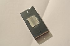
I took off the input and output capacitors, inductors, volume pot and screw terminals.
Then I proceeded to pry off the heatsink with a small flathead scewdriver, but it was well glued stuck.
When I finally manage to pry it off I noticed I wrecked the smd capacitor marked as C7.
I've looked at the schematic in the datasheet, and my best guess is that it is supposed to be the capacitor marked as C58 in the datasheet. Can anyone confirm this for me?
Attachments
Impressive modifications kokoriantz!
Given the scale of your changes, were you ever tempted just to make your own PCB?
I know the mass-produced boards are really cheap but it must have taken you a lot of time?
I have seen lots of people reporting start up/shut down plop with TPA3116 boards and various modifications to fix it but I have not experienced it. Not sure if it something about my red mono board, or that I have it wired-up balanced, rather than single-ended.
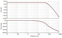
This is simpler but 4 times lower distortion than the precedent.
Nice!
Are you graphs based on simulations or have you built it?
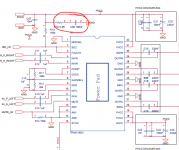
Simulation. The signal part, from my precedent experience is rather sure. The dc bias feedback, the spice model is not functioning, I only estimate from measurements but the stability is to review. With 1.2Mhz, AM2 on +, The response is still better. I configured it so to be able to apply the same on TPA3255.
Last edited:
Interesting approach. TPA3118 has the potential of loads of post-filter feedback thus widening frequ response and reducing THD significantly. This is due to the fact that you can program the amp gain to a high value - an option that the TPA325x lack. And these achievements are not only theoretically but have been verified in reality by me some time ago.
Did you post anything about it? To get back stability I reduced the frequency response more than necessary to obtain forth order Bessel, as I have nearly a constant delay verified at 2k and 20k. In the precedent version, I had to add an all pass to adjust the phase as I didn't used feedback.
I drive the inputs by high impedance current source, so the gain adjust which is the value of series resistor should not act much.
I drive the inputs by high impedance current source, so the gain adjust which is the value of series resistor should not act much.
Last edited:
- Status
- This old topic is closed. If you want to reopen this topic, contact a moderator using the "Report Post" button.
- Home
- Amplifiers
- Class D
- Sublimed TPA3116D2