I googled and found this, basically a simple circuit that mutes the amp
Final Solution for anti-pop on Sure TPA3116
TPA3132D2 - on-delay and emergency shut-down (anti-pop) - also for TPA3116 / TPA3118 - #360customs
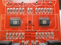
Dear Daijoubu, Thank you so much for your reply. As a matter fo fact, I am not that expert. Following either of these solutions could you please be a bit more specific and let me know to which chip I should apply the mod. There are two chips. I attach an image uploaded by one the members
(carpne) of this forum which is exactly my circuit. Thank you so much in advance.
Attachments
Last edited:
You'll have to do both as each is in PBTL and handles one channel (L and R)
Dear Daijoubu, I did apply the first mod HERE to the left channel only. It only delays turning on that channel. Now the left channel starts later than the right channel. However, the pop is still there for both channels, the right and the left. No difference at all. I can definitely say that this mod does not affect the turn off pop. It makes delay on turning on. I have no issue with turning on the amplifier. No pop .. nothing.
Member
Joined 2018
Dear CyberPit, Just a quick question. Should I apply this driver to data sheet (M190 circuit) or I should do some modifications before applying this? The pin 12 is connected to the GND with a 100k resistor. Thank you so much in advance.Hi farhad-San, If you like to try my Muting Driver circuit as follows...
Last edited:
Member
Joined 2018
Hi farhad-San,
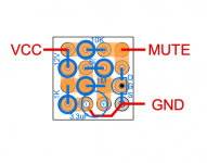
Just you need to do is remove 100K resistor then connect pin12 side land to the additional Mute Driver Board's MUTE output.
Just you need to do is remove 100K resistor then connect pin12 side land to the additional Mute Driver Board's MUTE output.
Last edited:
Hi farhad-San, If you like to try my Muting Driver circuit as follows...
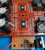
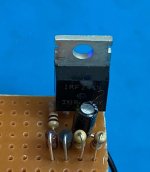
I should admit that it works.... yes, it works. This is the simplest solution for the turn-off thump problem I have ever found on the net. I should thank you so much CyberPit. I made one of these drivers and applied to one channel. That channel waits almost 4 sec before it starts. Then, when I turn the amp off that channel turns off without pop. Nothing at all. Dead silent 🙂. I should say that I did not have access to 2N7000 so I used JRFZ44 instead. Thank you again all you guys for helping me. This "Muting Driver Circuit" just works.... no turn-off thump at all for my module m190 or hw-303 V3. CyberPit your circuit is excellent. I appreciate your help.
Attachments
Last edited:
Hi farhad-San,
Just you need to do is remove 100K resistor then connect pin12 side land to the additional Mute Driver Board's MUTE output.
As a matter of fact I did not remove 100k resistor but it still works. By the way, should I make two of them (one for each channel) or I can use only one for both??
Member
Joined 2018
By the way, should I make two of them (one for each channel) or I can use only one for both??
Hi farhad-San,
I'm glad to hear that.
I guess you need only one driver board. It can drive two boards as well.
CyberPit: Two questions, 1- how can I decrease the waiting-time? It takes almost 4 sec to start the amp. and then the amp starts abruptly not smoothly. 2- what happens if I do not remove 100k resistor at pin 12. In fact I have not removed them yet and the driver works fine for both chips.Hi farhad-San,
I'm glad to hear that.
I guess you need only one driver board. It can drive two boards as well.
Member
Joined 2018
Hi farhad-San,
I will recommend decreasing the Capacitance method.
Power-OFF Muting will start when the VCC voltage bellows approx. 14 volt. If you change the Zenor Diode voltage, Muting start voltage-below will shifts simultaneously.
CyberPit
This Muting Driver Circuit has Power-ON Muting and Power-OFF Muting features. Power-On Muting uses a time to charge the 3.3uF Capacitor via 1M ohm resistor. So there are 2 ways to shorten that duration. One is to decrease the resistance of 1M ohm resistor, and the other way is decreasing 3.3uF Capacitor's Capacitance. If you change one of them to half then the Power-ON Muting Duration will be Half (=2sec).questions, 1- how can I decrease the waiting-time? It takes almost 4 sec to start the amp. and then the amp starts abruptly not smoothly.
I will recommend decreasing the Capacitance method.
Power-OFF Muting will start when the VCC voltage bellows approx. 14 volt. If you change the Zenor Diode voltage, Muting start voltage-below will shifts simultaneously.
Originally existing 100K resistor is not affect the Power-ON Muting Duration. But this resistor forms Voltage Divider with high-side 10K resistor. This means a voltage to mute TPA3115D2 will be lower than the removed case. A threshold voltage of the Muting function is 2 volt. Thus means driving voltage will decrease a little bit. So if you not remove this (100K ohm) resistor, but it is not a big matter.2- what happens if I do not remove 100k resistor at pin 12. In fact I have not removed them yet and the driver works fine for both chips.
CyberPit
Hi farhad-San,
This Muting Driver Circuit has Power-ON Muting and Power-OFF Muting features. Power-On Muting uses a time to charge the 3.3uF Capacitor via 1M ohm resistor. So there are 2 ways to shorten that duration. One is to decrease the resistance of 1M ohm resistor, and the other way is decreasing 3.3uF Capacitor's Capacitance. If you change one of them to half then the Power-ON Muting Duration will be Half (=2sec).
I will recommend decreasing the Capacitance method.
Power-OFF Muting will start when the VCC voltage bellows approx. 14 volt. If you change the Zenor Diode voltage, Muting start voltage-below will shifts simultaneously.
Originally existing 100K resistor is not affect the Power-ON Muting Duration. But this resistor forms Voltage Divider with high-side 10K resistor. This means a voltage to mute TPA3115D2 will be lower than the removed case. A threshold voltage of the Muting function is 2 volt. Thus means driving voltage will decrease a little bit. So if you not remove this (100K ohm) resistor, but it is not a big matter.
CyberPit
Dear CyberPit: I changed the 1M resistor with a 500K and the waiting-time is reduced as expected. The driver also works fine for both channels at the same time. However, I have two new challenges now:
1- The amp does not work with 12V-5A switching power supply. Although it works with a linear 12V-5A which is rectified (almost 17V-5A).
2- The module suffers from clipping at low frequencies (heavy bass). Do you have any idea why this happens? Is it related to the voltage? Or the decoupling caps?
Thanks.
Member
Joined 2018
1- The amp does not work with 12V-5A switching power supply. Although it works with a linear 12V-5A which is rectified (almost 17V-5A).
2- The module suffers from clipping at low frequencies (heavy bass). Do you have any idea why this happens? Is it related to the voltage? Or the decoupling caps?
Thanks.
I guess it depends on the supply voltage. My design was applied for DC19V regulated supply. Perhaps the LF distortion occurs on supply voltage drop point. If you want operate with regulated DC12V supply, you need to change the zener diode from 12V to 5.6V.
Hello CyberPit,
What characteristics should have elements of your muting driver circuit for a 24-volt power supply?
With regards.
What characteristics should have elements of your muting driver circuit for a 24-volt power supply?
With regards.
Member
Joined 2018
Hello CyberPit,
What characteristics should have elements of your muting driver circuit for a 24-volt power supply?
With regards.
No problem between form 19V through 24V.
I guess it depends on the supply voltage. My design was applied for DC19V regulated supply. Perhaps the LF distortion occurs on supply voltage drop point. If you want operate with regulated DC12V supply, you need to change the zener diode from 12V to 5.6V.
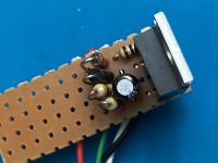
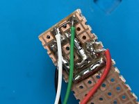
Hi CyberPit, Just wanted to confirm that using a zener diode 5.6V it works just fine with 12V switching power supply. Thank you so much. Just a question: is it possible to design the driver so it covers 12-24V?
Attachments
Last edited:
Hi CyberPit: After changing the Zener diode, the driver now works at both 12V and 19V.No problem between form 19V through 24V.
Attachments
Last edited:
Hi, could we use an N-channel FET instead of the 2N7000 MOSFET?
Member
Joined 2018
Hi, could we use an N-channel FET instead of the 2N7000 MOSFET?
Yes, if it is an enhancement-mode(normally off) device.
Last edited:
Hi CyberPit; The driver works just fine but there is a new issue I did not have checked before. At MAX volume (or very high volume) the amp module switches between mute and un-mute states so the out put sound starts and stops repeatedly. Kind of turning on and off the amp very quickly. This does not happen at low volume. Do you have any idea why? Does it have anything to do with input voltage? Thank a lot.No problem between form 19V through 24V.
- Home
- Amplifiers
- Class D
- 2x100W TPA3116D2 (2 chips, each in PBTL)