definitely EMI as well
Yes, but how could have generate variable difference freq? f-f=0! And why only at 150-200-250-300-350 kHz? There must be an 50 kHz (and harmonics) signal source!
Leigh! Was the SMPS really totally disabled?
I do have a 7805 reg, and to make matters worse this reg follows an lm switching reg that just happenZ to switch at around 50Khz. Can it be that obvious??
I doubt it as i have run the amp without the switching reg and there was no difference, the noise was still there. The 7805 reg was still in place tho. There are also two DC-DC converters on board. They seem clean and are well decoupled. Maybe i'm being a bit picky here. The noise is very low in the background and i'm pretty sure it will be below the noise floor when i go closed loop. Maybe i'm at the limit of this technology. If this is a design error i'd like to fix the problem properly rarther than simply covering it up with feedback
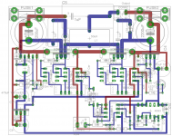
Even though i have not done a schematic yet i have my proto PCB layout that i can attach so you have an idea how things are wired and you can work out the schematic from that. I'll post an actual schematic this weekend. The layout shows ground tracks but on the physical board the entire bottem layer is one large copper area as in the photos above.
I doubt it as i have run the amp without the switching reg and there was no difference, the noise was still there. The 7805 reg was still in place tho. There are also two DC-DC converters on board. They seem clean and are well decoupled. Maybe i'm being a bit picky here. The noise is very low in the background and i'm pretty sure it will be below the noise floor when i go closed loop. Maybe i'm at the limit of this technology. If this is a design error i'd like to fix the problem properly rarther than simply covering it up with feedback
Even though i have not done a schematic yet i have my proto PCB layout that i can attach so you have an idea how things are wired and you can work out the schematic from that. I'll post an actual schematic this weekend. The layout shows ground tracks but on the physical board the entire bottem layer is one large copper area as in the photos above.
Attachments
the only other thing that is switching in the room is the fet bridge
There are also two DC-DC converters on board.
They seem clean and are well decoupled.
Do you really think they are isolated from the carrier or PWM signal for at least 80 dB ?!? How could you possibly know? Are you able to see 10 micrometer untriggered signal fluctuations on your scope???
I can see most things on my scope. Not sure what you mean by 10 micrometer??
But if the two DC-DC converters were causing the intermodulation then there would be more than one tone as there are two converters and the tones would interfere with each other too. It would cause a real mess. This may sound stupid but does anyone think 50Hz mains could be a culprit here??
Leigh
But if the two DC-DC converters were causing the intermodulation then there would be more than one tone as there are two converters and the tones would interfere with each other too. It would cause a real mess. This may sound stupid but does anyone think 50Hz mains could be a culprit here??
Leigh
there would be more than one tone
1: not neccessarily perceptable both.
2: I do hear two tones!
and the tones would interfere with each other too
Not really. (They do, but you don't have any chance to notice it.)
The diodes in RD networks after comparator on the layout are directed in wrong way... In this direction this will work for charging of capacitor (before optocoupler), and discharging will be done via resistor... Is it in your real prototype so too?
And where are your bypass cpacitors after DC-DC converters?
And where are your bypass cpacitors after DC-DC converters?
Last edited:
The DC-DC converters are well decoupled with tantalum caps directly on the base of the MAX626 driver ic, and also the IL711 magnetic coupler. I have used them before like this with no problems. However i must say there is too much of a coincidence that the running freq of these converters is approx 50KHz. Common sense forces me to think these converters could be the source of the noise. I'll whip them out this weekend and try some fancy bootstraping to see if the problem vanishes. Just because i have used them successfully in other amps doesnt mean that they are not interfering on this occasion. I really cant think of any other noise source, Well spotted Pafi.
Regarding the diode directions, they are correct. Yes, this is a real working prototype. The diodes and resistors set my dead time.
I'll let you know if bootstraping solves the noise issues, won't be till weekend tho... time is a premium this end LOL
Leigh
Regarding the diode directions, they are correct. Yes, this is a real working prototype. The diodes and resistors set my dead time.
I'll let you know if bootstraping solves the noise issues, won't be till weekend tho... time is a premium this end LOL
Leigh
Regarding the diode directions, they are correct.
Yes, agree... This is because of inverting MAX626...
Also, simply interesting, do you see any ringing on this prototype?
Hardly any ringing at all, See the waveforms earlier in the thread. They are very clean
Absence of the ringing with big deadtime under NO load says nothing for me. Please, try to give some load (say 2-3 amperes), so the body diodes will enable during the deadtime, and post the waveforms here.
Deadtime is only 50n/s... I thought that was quite small LOL
There was no load tho... I'll load it up to 200W and see if it changes things, if it does i'll post the waveforms. I've burnt it in at full power for over 10min's before now and i cant remember seeing anything dodgey in the square.. i'll certaintly check for you tho..
Leigh
There was no load tho... I'll load it up to 200W and see if it changes things, if it does i'll post the waveforms. I've burnt it in at full power for over 10min's before now and i cant remember seeing anything dodgey in the square.. i'll certaintly check for you tho..
Leigh
Now the switching is half hard, half quasi-resonant, the second half is hard, and seems to be very fast, so the fact that ringing doesn't appear gives hope to work well also at full load, but the slow body diode of IRF640 will make losses relatively high. With music and real speaker there won't be a problem, but a continuous full current test may show more. (And waveform will change significantly for sure.) BTW: What is the bandwidth of scope and probe? Yesterday I explored a strong 240 MHz ringing in one of my amps despite the switching was not really fast (30-40 ns rise and fall time).
What is n/s?
What is n/s?
Ok,
Over the weekend i've had time to remove all switching PSU's one by one. I started by again removing the LT25XX switchin reg with a 12v SLA battery. No effect. I then replaced the low side DC-DC converter with Ni-cad memory backup battery's. No effect. I then romoved the last DC-DC converter. Also no effect at all on the whistling noise. Its definatly sensitive to having a finger near the cmos nand gates. Also sensitive to touching the low side fet. Apart from those two hot spots you can literally lick the board when its operating and have no effect on the whistle. It must be the main carrier some how getting back into the modulator.
I'm gonna put all the power supplies back to normal over the next few nights and think of somthing else. Very strange indeed. I may have to submit and go with self osc topology, or just close the loop and pretend its not there
Oh yeh.. Loading. When loaded up with a 4R resistive load and 1K sine the amp delivers full power at about +-42V Pk before cliping, 218W RMS, 7.4A Pk ( by calculation ). The only effect on the square is a 3V increase in overshoot spike. Nothing worth posting.
Has anyone any other thoughts on what can be causing the intermodulation noises? I'm about all out of ideas
Leigh
- Status
- This old topic is closed. If you want to reopen this topic, contact a moderator using the "Report Post" button.
- Home
- Amplifiers
- Class D
- Producing Triangle Waves