Peter Daniel said:
I remember jcarr was saying that same diodes from different manufacturers sounded different. I wouldn't be surprised.
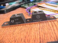
MUR1520 I'm using, are IR parts. My comments regarding directionality of the diodes was a joke.")
As was my comment. Diodes are the only things I am sure of are directional as that is what they are supposed to be...
I checked the cable from PS to the amp. I'm using 8 wires, 4 per channel; positive rail, negative rail and separate grounds for ea. It seemed like the good choice would be Kimber 4TC speaker cable. I also tried a cable made of 8 wire runs of silver plated, stranded copper. To my surprise both cables had very distinctive and different sonic signature. The Kimber sounded very clean, with very good resolution at top end and somewhat lean and laid back. The silver plated teflon wire on the other hand was more warm, tuby with more midrange texture, but not really clean sounding. It was sounding good with classical and jazz material, while Kimber was good for the rock music. I still didn't make my mind as to which one to choose, although I'm biased towards Kimber.
Now, this is only a PS wire, yet it makes the same difference as speaker cable or interconnects.
Now, this is only a PS wire, yet it makes the same difference as speaker cable or interconnects.
Are you talking about the supply rail caps, or the input cap?Peter Daniel said:so I replaced them with 4.7u BG N. I suspect that this is better choice, because it didn't loose any naturalness of the sound (what I felt eith extra 1000U) and both bass and highs definition are improved. I think I will keep those ones.
--Jordan
Peter Daniel said:good choice would be Kimber 4TC speaker cable. I also tried a cable made of 8 wire runs of silver plated, stranded copper. To my surprise both cables had very distinctive and different sonic signature.
A candidate for trial would be the ubiquitous Cat 5 EN cable -- convieniently 8 strands. Just like people doing speaker cable you could gang up multiple runs to get whatever guage you wanted.
dave
Peter,
You can get it at a computer store, or any number of online distributors. What you want is "plenum rated" Cat 5 wires, they have teflon insulation and sound much better than the usual Cat5. For the best performance, remove the wire pairs (four twisted pairs of 24awg) from a few lengths of cable and braid it like this: http://www.venhaus1.com/diycatfivecables.html It sounds really good.
You can get it at a computer store, or any number of online distributors. What you want is "plenum rated" Cat 5 wires, they have teflon insulation and sound much better than the usual Cat5. For the best performance, remove the wire pairs (four twisted pairs of 24awg) from a few lengths of cable and braid it like this: http://www.venhaus1.com/diycatfivecables.html It sounds really good.
Arf. What makes a Cat 5 cable cat 5 is not just the wires but the precise number of twists per inch and arrangment of the signal wires and corresponding grounds. If you take it all apart and braid cables together it may sound good, but you've lost the precision that makes the cable Cat 5.
Planet10 has a bit of study done on his site on Cat 5 that could help explain why it is good as signal cable.
Planet10 has a bit of study done on his site on Cat 5 that could help explain why it is good as signal cable.
Kilentra said:You can get it at a computer store, or any number of online distributors. What you want is "plenum rated" Cat 5 wires, they have teflon insulation and sound much better than the usual Cat5. For the best performance, remove the wire pairs (four twisted pairs of 24awg) from a few lengths of cable and braid it like this: http://www.venhaus1.com/diycatfivecables.html It sounds really good.
The plenum grade (doesn't cause toxic fumes when it burns) is generally considered best for signal use, but who knows how it compares to the cheaper PVC coated for power supply lead.
I get most of mine as scrap -- i often use a single seperated pr of wires as speaker cable in more efficient speakers. The key to its success is that it is very pure copper & because of the huge amounts being sold into data systems it is cheap.
I also have a big batch of Cat 3 (?), thicker, older wire, i pulled out of a ceiling when we were wiring up an architects office that i find quite useful (from speaker wire to twist tie substitutes).
dave
Peter,
In your GainKlone schematic, are the 1,000uF BG's rated
50V or 25V? I guess you'd have to go with 50V if your
secondaries are 25V.
the 50k resistor - is 1/4 watt? Holco, Riken?
and one more...
if the toroid i'm using is 230VA what should your diode bridge
be rated at?
In your GainKlone schematic, are the 1,000uF BG's rated
50V or 25V? I guess you'd have to go with 50V if your
secondaries are 25V.
the 50k resistor - is 1/4 watt? Holco, Riken?
and one more...
if the toroid i'm using is 230VA what should your diode bridge
be rated at?
Cat 5 as speaker cable
But I'm afraid you are losing the point here. What you are doing when you take apart the Cat 5 wires and braid them as explained on that article is a new cable.
It might be said that you used just the wires but not the original Cat 5 arrangement.
The problem is that the Cat 5 outer insulation is pvc, even on the plenum types, and if you braid it all together the pvc will then become dielectric, and pvc it's not considered a good dielectric.
That said, I must add that I did listen to braids using three or four Cat 5 cables which still had the PVC insulation and they sounded much better than other cables like Monster, etc.
But reports from people that built that "unsheated" Cat 5 cables said they are the equal or better than many top cables. Making those big braids is difficult and painful however.
There's a way out that would not compromise things too much though: a 25-pairs cable which is twisted exactly as the Cat 5 but within the same pvc insulation. You can make your left and right cables using them.
It's not easy to find and it's not cheap. Belden makes two types that can be considered good: #1864A and #1871A. The internal wires are polypropylene and FEP respectively, which are considered good dielectrics.
Carlos
tiroth said:Arf. What makes a Cat 5 cable cat 5 is not just the wires but the precise number of twists per inch and arrangment of the signal wires and corresponding grounds. If you take it all apart and braid cables together it may sound good, but you've lost the precision that makes the cable Cat 5.
Planet10 has a bit of study done on his site on Cat 5 that could help explain why it is good as signal cable.
But I'm afraid you are losing the point here. What you are doing when you take apart the Cat 5 wires and braid them as explained on that article is a new cable.
It might be said that you used just the wires but not the original Cat 5 arrangement.
The problem is that the Cat 5 outer insulation is pvc, even on the plenum types, and if you braid it all together the pvc will then become dielectric, and pvc it's not considered a good dielectric.
That said, I must add that I did listen to braids using three or four Cat 5 cables which still had the PVC insulation and they sounded much better than other cables like Monster, etc.
But reports from people that built that "unsheated" Cat 5 cables said they are the equal or better than many top cables. Making those big braids is difficult and painful however.
There's a way out that would not compromise things too much though: a 25-pairs cable which is twisted exactly as the Cat 5 but within the same pvc insulation. You can make your left and right cables using them.
It's not easy to find and it's not cheap. Belden makes two types that can be considered good: #1864A and #1871A. The internal wires are polypropylene and FEP respectively, which are considered good dielectrics.
Carlos
moe29 said:Peter,
In your GainKlone schematic, are the 1,000uF BG's rated
50V or 25V? I guess you'd have to go with 50V if your
secondaries are 25V.
the 50k resistor - is 1/4 watt? Holco, Riken?
and one more...
if the toroid i'm using is 230VA what should your diode bridge
be rated at?
1,000u's are rated 50V. I didn't use 50 k resistor, but the Alps pot. You can try either one and see how it sounds. You'll by 4 Holcos for the price of 1 Riken. I found Holcos not bad, but look for all non magnetic style.
The bridge doesn't have anything to do with rating of transformer. It should be safe enough for amps current draw. I used as low as 4 A but at least 8A is eecommended and 15A might sound even better. As I said before I like MUR1520 for rectifiers. You'll need 8 of them.
25 V for the caps is too low in either case (unless you use 12 Vac toroids or so).
I would really like to get some plenum rated CAT5, but I haven't found it here in the Netherlands
I can buy some 47labs cable though, but that's quite expensive. Now, I use two pair of CAT5 per channel as speaker cable.
Peter: you could try the dual schottky's I use !? I did not compare it to other diodes, but they should be very good. (they really should be seen the cost!)
Here's the info:
Dual Schottky 100V, 2x10A, 996-385 (Farnell)
STPS20H100CT
Fedde
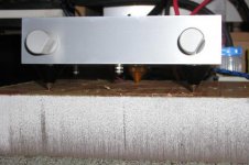
This is my last improvement for today. I installed 3 improved spikes under my amp and I couldn't believe the improvement in sound.
While I had some doubts if Kimber cable was OK, or diodes were not too soft in trebles, after the spike installation everything just got right into focus and now I understand what they mean when saying that soundstage opened up. Everything became so coherent and right that the big smile still didn't disappear from my face.
I was listening to old recordings and was discovering them again, hearing new sounds that I was not aware before (and I'm not kidding).
Now, if you look carefully there are two steel spikes in front and one in the back. The one in the back is brass and I put it there on purpose. While steel spikes provided very nice bass extention and definition the top end was a bit too harsh. Substituting one of them with a brass spike, made everything sound smoother and
more pleasing. The spikes are highly recommended. The amp is resting on 2.5" acrylic board.
moderator's note: this post engendered a long side discussion moved here: http://www.diyaudio.com/forums/showthread.php?s=&threadid=11742&perpage=15&pagenumber=1
planet10
. While I had some doubts if Kimber cable was OK, or diodes were not too soft in trebles, after the spike installation everything just got right into focus and now I understand what they mean when saying that soundstage opened up. Everything became so coherent and right that the big smile still didn't disappear from my face.
I was listening to old recordings and was discovering them again, hearing new sounds that I was not aware before (and I'm not kidding).
Now, if you look carefully there are two steel spikes in front and one in the back. The one in the back is brass and I put it there on purpose. While steel spikes provided very nice bass extention and definition the top end was a bit too harsh. Substituting one of them with a brass spike, made everything sound smoother and
more pleasing. The spikes are highly recommended. The amp is resting on 2.5" acrylic board.
moderator's note: this post engendered a long side discussion moved here: http://www.diyaudio.com/forums/showthread.php?s=&threadid=11742&perpage=15&pagenumber=1
planet10
Attachments
Peter, if you want to try some different diodes, I have some 200A 200-400v ultra fast diodes if you want some. I got them as samples a while back. I can mail you up 8 of them if you want to try them out.
http://www.onsemi.com/pub/Collateral/MURP20020CT-D.PDF
--
Brian
http://www.onsemi.com/pub/Collateral/MURP20020CT-D.PDF
--
Brian
Attachments
Rookie said:I never understood how mechanical damping can improve the sound of an amplifier. It is perfectly valid with turntables, speakers and other electromechanical devices, but amplifiers and preamplifiers? How can a mechanical vibration affect the work of resistors, capacitors, op-amps, etc.? Is there a valid technical explanation for this, or is this just another audio black magic?
transformers can vibrate on heavy load
but for all other components, I agree with you

Just a question: my gainclone project uses 2200µF per chip and per rail, just between the diode bridges and the chips
is this enough? it's so much less than the 60 000 + on alephs
Well , since there seems a lot of testing and tweaking going on I guess I'll jump in with this.
So after all the buzz about the BG L-cancelling super E configuration I thought it would be a good experiment on the gainclone since the caps don't have to be big. I used 680uF 35V Nx type .This is x 2 on each polarity for a total of 1360uF. I compared this to 4700uF BHC Aerovox on the pins . I know that Bgs need a lot of break in so this is still an initial impression after about 10hrs and at 20 hrs there was a small improvement.
I preferred the BGs, they seemed to bring out mid-bass and mid-range more. There was more depth/separation between vocals and instruments and generally a more rhythmical presentation.I didn't notice much difference in the top end.I would say that the differences were not huge so if you don't have the budget for them I wouldn't sweat it. This test is not very comprehensive since the ideal would be to use a normal Panasonic 1000uf cap then compare a similar size standard BG cap then perhaps the 4700uf cap then the 680uf on its own . But I really don't have the time and extreme patience(50 hrs on resistor directivity!) that some of you have. Just the A/B ing that I did on music took like an hour to be sure of what I was hearing.
In any case I will report back as soon as I feel the BGs have broken in substantially.
Carlmart:
>I don't understand why this prehistoric assembly fashion [point to point] is still preserved, as you can do short paths using pcb techniques too, and damping is automatic when you insert a part on a pcb.<
Both circuit board and point-to-point "air-dielectric" constructions have their strong points and weak points. Circuit-board layout allows you to use ground-planing and impedance control, is better for securing moderately heavy components, and is far more production-friendly. Air dielectric offers much lower levels of leakage currents and parasitic capacitances, and the circuit can be _much_ more compact (because the construction can be 3-dimensional instead of only two).
You may ask, what about a better board material than FR4, such as teflon? It is true that teflon has much lower levels of leakage currents and parasitic capacitances, and damping is also better. But mechanically it is weak (enough so to be a problem), and the construction is still limited to two dimensions.
In my experience, the best results are obtained by combining circuit board with air-dielectric constructions. I am currently using a sandwich of two 4-layer circuit boards, spaced just far enough apart to allow components to be installed between the boards. Each board has full ground and power planing, the sensitive circuit nodes are built as air-dielectric structures spaced away from the board, and the air-dielectric techniques allow me to stack components on top of each other. For circuit traces, this construction gives me 8 board layers and another couple of "layers" in the air, and for installing components, I have 4 board layers plus additional air layers.
The sound quality?
Sufficient.
jonathan carr
jcarr said:The sound quality?
Sufficient.
jonathan carr
A very modest answer from a very modest designer.
I cannot help doing some speculation on the two methods.
A component soldered to a PCB will be attached very stiffly
unless using long and/or bent legs. Most likely, the whole
PCB will be affected by vibrations, forcing all its components
to resonate with the board. This might cause mechanical
tension in the components, affecting their electrical properties
as previoously discussed. On the other hand, I would think
that p-p soldered components form a much more flexible
mesh, with a lot of damping between components which
will a) make each component to tend to resonate at its own
frequency (not necessarily a good thing) and b) the flexibility
of the joints will functiion as damping of resonances, which
should be a good thing.
These are only theoretical speculations, that may or may not
be near the truth. If anyway attempting to draw some conclusions
from them, I would say that: P-p soldered components might
be more susceptible to high-frequency vibrations, but resonances
will also die out much quicker. PCB mounted components might
be excessively affected by low frequency vibrations, since they
will be forced to follow the resonances of the whole populated
PCB. Depending on the distribution and mass of the components
on the PCB, certain frequencies may tend to die out or be
sustained.
- Status
- This old topic is closed. If you want to reopen this topic, contact a moderator using the "Report Post" button.
- Home
- Amplifiers
- Chip Amps
- This is not just another gainclone