Hello, Everybody.
How are you doing?
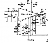
I'm designing an STK4231II amplifier, with an original part that I have for more than 20 years and never used (precious!") . Just to relax, rsrs.
. Just to relax, rsrs.
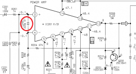
I started with the Sanyo's reference design, to calculate gain, poles, bandwidth, protection, etc, with further reading of some services manuals, just to see what there is out there, and I found something curious that I can't explain well. On the services manuals (more than one), the designers have placed a small capacitor across STK's inverting and non inverting inputs. After some matlab and LTSpice, this capacitor creates an additional pole at around 40MHz, using an ideal model of an operatinal amplifier.
Does anybody know the reason for this spending? Maybe for susceptibility compatibility? The designer has placed this small capacitor across all the operational amplifiers he/she used in the equipment
How are you doing?
I'm designing an STK4231II amplifier, with an original part that I have for more than 20 years and never used (precious!
. Just to relax, rsrs.I started with the Sanyo's reference design, to calculate gain, poles, bandwidth, protection, etc, with further reading of some services manuals, just to see what there is out there, and I found something curious that I can't explain well. On the services manuals (more than one), the designers have placed a small capacitor across STK's inverting and non inverting inputs. After some matlab and LTSpice, this capacitor creates an additional pole at around 40MHz, using an ideal model of an operatinal amplifier.
Does anybody know the reason for this spending? Maybe for susceptibility compatibility? The designer has placed this small capacitor across all the operational amplifiers he/she used in the equipment
Attachments
My best guesses are that it is either to try and reduce RF pickup (stop the amp demodulating powerful AM radio stations and/or it is an attempt at increasing the noise gain of the chip which can aid stability and help when driving capacitive loads.
You would normally have a series resistor with the cap though when doing that.
You would normally have a series resistor with the cap though when doing that.
- Status
- This old topic is closed. If you want to reopen this topic, contact a moderator using the "Report Post" button.