Hi, all.
I've obtained an old and used, but still working, pair of Spirit Absolute 4p studio monitors. They were really cheap, and, for nostalgic reasons, I wanted them. But they need some love.
They work and play, but both exhibit some hum and "tzzzzz" and they pop and click quite loudly when powering up and down.
Is this a matter of just replacing all the electrolytic capacitors? There aren't many in the amps, according to the service manual.
I've tried to manually copy/paste the schematics to .PNG's and attach them to this post.
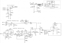
As far as I'm able to interpret the schematics, there are no electrolytic caps in the "turn on/off mute circuit", nor are there any of interest in the woofer and tweeter protection circuits. I thinks those are based on optocouplers, that "short" the positive and negative inputs of the respective amps, thus lowering the outputs. But I could be wrong. I would suspect, however, that a any start-up delay would mute the woofer and tweeter so as to block any pops and clicks from the drivers. What could be the cause of this not working properly? Is this easily fixed (i.e. replacing a few parts)?
Hope you can help!
Thanks!
James.
I've obtained an old and used, but still working, pair of Spirit Absolute 4p studio monitors. They were really cheap, and, for nostalgic reasons, I wanted them. But they need some love.
They work and play, but both exhibit some hum and "tzzzzz" and they pop and click quite loudly when powering up and down.
Is this a matter of just replacing all the electrolytic capacitors? There aren't many in the amps, according to the service manual.
I've tried to manually copy/paste the schematics to .PNG's and attach them to this post.
As far as I'm able to interpret the schematics, there are no electrolytic caps in the "turn on/off mute circuit", nor are there any of interest in the woofer and tweeter protection circuits. I thinks those are based on optocouplers, that "short" the positive and negative inputs of the respective amps, thus lowering the outputs. But I could be wrong. I would suspect, however, that a any start-up delay would mute the woofer and tweeter so as to block any pops and clicks from the drivers. What could be the cause of this not working properly? Is this easily fixed (i.e. replacing a few parts)?
Hope you can help!
Thanks!
James.
Attachments
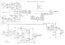
Regarding the power/on-off pop noises, I would direct my attention to C116-C117.
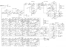
Loud hum/buzz most likely indicates that the 10000µ caps (C9/10) have seen better days, and possibly bootstrap capacitors C102-105 as well. Just make sure it's not mechanical though, and verify that both regulators are actually putting out their +/-16.5 V as they should, since results would be less than pretty if one were dead.
This is getting quite close to a full recap, isn't it? I wonder what they were using for capacitors, nothing first-grade I suspect. Either that, or they had a lot of active use. These look to be a bit over 20 years old?
I'd say proceed with that and see where you get from there. I would not expect a designer cautious enough to properly distinguish between chassis ground and signal ground (and connect XLR pin 1 in line with modern standards!) to make severe power supply PCB routing mistakes, but you never know.
Once you have this sorted out, I would take a listen to tweeter hiss levels, given that all power amps look to be identical.
Thanks for your reply!
I am planning to replace all electrolytic caps. I suspect that there can't be much wrong with the non-electrolytics, right?
Somebody else told me that, before I replace any part, I should determine if it's a low-ESR version, or not. Since ESR might be employed to combat parasitic resonances. How do I figure out what part is used where and why? I suspect I could safely use "generic" parts..? (Nichicon, Panasonic, Rubycon and such).
I'm not quite sure what you mean by the bold text. I'm not that well versed in electronics.Regarding the power/on-off pop noises, I would direct my attention to C116-C117.
Loud hum/buzz most likely indicates that the 10000µ caps (C9/10) have seen better days, and possibly bootstrap capacitors C102-105 as well. Just make sure it's not mechanical though, and verify that both regulators are actually putting out their +/-16.5 V as they should, since results would be less than pretty if one were dead.
This is getting quite close to a full recap, isn't it? I wonder what they were using for capacitors, nothing first-grade I suspect. Either that, or they had a lot of active use. These look to be a bit over 20 years old?
I'd say proceed with that and see where you get from there. I would not expect a designer cautious enough to properly distinguish between chassis ground and signal ground (and connect XLR pin 1 in line with modern standards!) to make severe power supply PCB routing mistakes, but you never know.
Once you have this sorted out, I would take a listen to tweeter hiss levels, given that all power amps look to be identical.
I am planning to replace all electrolytic caps. I suspect that there can't be much wrong with the non-electrolytics, right?
Somebody else told me that, before I replace any part, I should determine if it's a low-ESR version, or not. Since ESR might be employed to combat parasitic resonances. How do I figure out what part is used where and why? I suspect I could safely use "generic" parts..? (Nichicon, Panasonic, Rubycon and such).
Last edited:
QUOTE=Jamesblond;6154710]I'm not quite sure what you mean by the bold text. I'm not that well versed in electronics.[/quote]
Hum and buzz can also be introduced by a bad layout in the power supply section (e.g. taking your star ground exactly between filter capacitors where the charge currents are passing through), and the best capacitors in the world couldn't fix that.
The Pin 1 Problem ultimately is much about the same thing. Chances are, if you are aware of one than you are likely to get the other one right, too.
That said, I would want to make some minor adjustments:
1. C116-C119 seem less generously sized in voltage handling than some of the others. Ideally, you want it to be between 150% and 300% of actual sustained voltage, not just a hair over.
2. I could see use for lower than usual ESR (e.g. Panasonic FR series) in the bootstrap capacitors, C102-105.
3. Then there's the whole subject of coupling capacitors that are never going to see appreciable DC, are where polarity is uncertain.
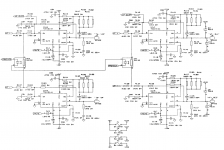
a) For C11 I would consider either a Nichicon Muse or their low-leakage series (UKL). Their bipolars have relatively high leakage current specs for some reason, which suggests a "rough" dielectric type.
b) Not sure why C11 is a 33µ/16 rather than, say, a 10µ/50, which would be much the same size and still more than sufficient given the 47k input impedance and 1k series resistance following. You'd also rather want a bipolar in a position like this. If you can fit a DIY bipolar (two polars end-to-end) in there at all, I'd consider that. I'd probably trust a construction with two FCs more than the Nichicon bipolars long-term.
c) C12/13 are similar. You ideally want those to be bipolar and relatively well-matched to boot (or at least oversized to the point where matching isn't a major issue, which is why they are relatively high capacitance to begin with). I'd say see what kind of space you've got there.
Hum and buzz can also be introduced by a bad layout in the power supply section (e.g. taking your star ground exactly between filter capacitors where the charge currents are passing through), and the best capacitors in the world couldn't fix that.
The Pin 1 Problem ultimately is much about the same thing. Chances are, if you are aware of one than you are likely to get the other one right, too.
With few exceptions, through-hole film and ceramic disc capacitors are very reliable indeed. It took the combination of surface-mount ceramic capacitors and lead-free solder to change this, several years after these speakers were produced.I am planning to replace all electrolytic caps. I suspect that there can't be much wrong with the non-electrolytics, right?
I would guess that there isn't a single Low-ESR cap in this device. You are more likely to find low leakage parts instead. You could probably stuff everything with a good all-round series like Panasonic FC (and the filter caps with the usual suspects for those like TDK / Epcos / whatever) and things would work fine. The most critical factor probably is mechanics - ideally, measure what's in there and the required pin pitch / configuration (the big filter caps could have more than two pins). If you can get parts with slightly higher voltage handling in there nowadays, all the better. Are the caps in there even through-hole types or are they SMD already as well?Somebody else told me that, before I replace any part, I should determine if it's a low-ESR version, or not. Since ESR might be employed to combat parasitic resonances. How do I figure out what part is used where and why? I suspect I could safely use "generic" parts..? (Nichicon, Panasonic, Rubycon and such).
That said, I would want to make some minor adjustments:
1. C116-C119 seem less generously sized in voltage handling than some of the others. Ideally, you want it to be between 150% and 300% of actual sustained voltage, not just a hair over.
2. I could see use for lower than usual ESR (e.g. Panasonic FR series) in the bootstrap capacitors, C102-105.
3. Then there's the whole subject of coupling capacitors that are never going to see appreciable DC, are where polarity is uncertain.
a) For C11 I would consider either a Nichicon Muse or their low-leakage series (UKL). Their bipolars have relatively high leakage current specs for some reason, which suggests a "rough" dielectric type.
b) Not sure why C11 is a 33µ/16 rather than, say, a 10µ/50, which would be much the same size and still more than sufficient given the 47k input impedance and 1k series resistance following. You'd also rather want a bipolar in a position like this. If you can fit a DIY bipolar (two polars end-to-end) in there at all, I'd consider that. I'd probably trust a construction with two FCs more than the Nichicon bipolars long-term.
c) C12/13 are similar. You ideally want those to be bipolar and relatively well-matched to boot (or at least oversized to the point where matching isn't a major issue, which is why they are relatively high capacitance to begin with). I'd say see what kind of space you've got there.
Thanks for your elaborate reply! Nice!
I've read the linked "pin 1 problem article", but frankly I have no idea how to determine if and how it's tackled in these monitors. I'll power them up with nothing connected and determine how quiet they are. Next, I'll connect open mic cables and listen again. Last, I'll connect those cables to my audio interface and listen again.
As for the electrolytic capacitors: there are some SMD types, but I haven't yet figured out what those are. Probably non-electrolytic. The PSU filter caps are two-pin through hole-types, if I am correct. The rest of the electrolytics are miniature through-hole types. They are small, because there is very little room. It's a bit difficult to explain why, except that the pcb is mounted very close to the amplifier mounting plate and heat sink. It's a dual layer affair and the electrolytic caps are on the "wrong" side. The filters and phase compensation seem to have been done with SMD components.
The fact that there is so little room, makes DIY'ing a bipolar caps quite unlikely.
I'll try to upload some images later.
I've powered up the speakers with no cables connected, both exhibit some mains hum, though not very loud, which could indicate the PSU filter caps need replacing. I'm probably going to do that anyway.
There is some tweeter hiss, a bit too loud for my liking, but nothing really suprising. When I crank up the input sensitivity, it gets slightly louder. Though more so on one speaker. One of both also produced some other noises when manipulating the input pot. Could be it needs cleaning.
When I connect a cable to the XLR input, nothing changes. Same behaviour for both speakers.
When I connect the other end of those cables to my audio interface, still no change. I suppose that's good.
When I feed them audio, I'm a bit startled by the high-end. I find it to be a bit agressive and "shouty". I'm used to Adam S2X's, so not really a fair fight, but still. I've replaced the domes of the tweeters, bacause they were almost pulverized. I have not yet replaced the ferrofluid, but have removed the old ferrofluid. The current sound could be a result of the new, not broken in and non-ferrofluid-damped tweeter domes. There is a good sense of front to back in the sound stage, but in my current test setup I can't really make any serious judgement on sound quality. My home studio is being built and it's a huge mess at the moment. I would really like to test these speakers in the acoustics of my studio space. But that will have to wait a while.
Still, as it is, the Spirits play okay. Bass seems a bit limited, but that's probably more of design issue than ageing. And in these acoustics, who can seriously tell..?
I'll tear them down and see what we're dealing with component-wise, so that I know what parts I will have to order. I'll also make some photos and post them here.
Last edited:
One more thing, though. Before tearing them down, I checked if I still had some thermal compound. Because will need that when putting them back together. I don't have any, so I'll have to order new.
The chip-ams themselves are mounted on a T-bar with silicone pads. But the T-bar is mounted on the heat sink with thermal paste.
Which one should I get? Is the higher W/m.K number better? How high should it be? 1.xx? 3.xx?
All quite expensive, by the way...
The chip-ams themselves are mounted on a T-bar with silicone pads. But the T-bar is mounted on the heat sink with thermal paste.
Which one should I get? Is the higher W/m.K number better? How high should it be? 1.xx? 3.xx?
All quite expensive, by the way...
Attachments
Last edited:
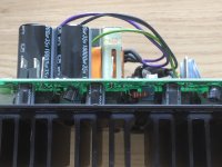
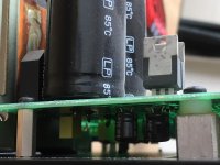
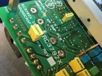
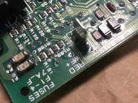
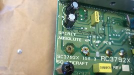
I took out the amplifier and found I didn't have to totally dismantle it to determine what's inside. I've attached some pictures.
As far as I can tell, all electrolytic caps are made by Jamicon. That name doesn't ring any bells.
We see C1 and C11/12 on the input board. Here there might be room for someting physically larger if that's easier to obtain.
We see C14/14, part of the PSU and mounted on the opposite side of the main filter caps. These, and all the others, are small. I'm not sure if they could/should be replaced with panasonic KS-series or similar, or if I should just look for physically small Panasonic/Nichicon/Rubycon parts.
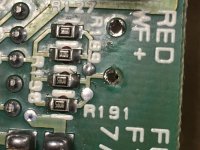
We also see the bootstrap C's (C116-119), which are in fact 50V parts, not 25V. The larger parts next to the bootstrap C's are C102-105.
All pin pitches are 5mm or smaller, except main PSU filter caps, of course.
Any suggestions on which parts/series to order?
As far as I can tell, all electrolytic caps are made by Jamicon. That name doesn't ring any bells.
We see C1 and C11/12 on the input board. Here there might be room for someting physically larger if that's easier to obtain.
We see C14/14, part of the PSU and mounted on the opposite side of the main filter caps. These, and all the others, are small. I'm not sure if they could/should be replaced with panasonic KS-series or similar, or if I should just look for physically small Panasonic/Nichicon/Rubycon parts.
We also see the bootstrap C's (C116-119), which are in fact 50V parts, not 25V. The larger parts next to the bootstrap C's are C102-105.
All pin pitches are 5mm or smaller, except main PSU filter caps, of course.
Any suggestions on which parts/series to order?
Attachments
Last edited:
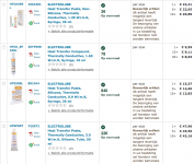
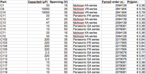
Unless there are any objections against this parts list, I think I'm good to go.
Nichicon KA- and VR-series, Panasonic GA- and FR-series.
As far as I can tell, there are little to no differences. But I went with the given advice above. Other than that, I chose highest thermal rating, small package and availability by single units, not reels of 2000 pieces.
Nichicon KA- and VR-series, Panasonic GA- and FR-series.
As far as I can tell, there are little to no differences. But I went with the given advice above. Other than that, I chose highest thermal rating, small package and availability by single units, not reels of 2000 pieces.
Attachments
As for C1, C12/C13 (which are at the input) and C11: can safely I use Panasonic SU-Bipolar series capacitors there? Will that affect sonics in any appreciable way?
......yes, i would change old (probably dried out) elcaps in the signal path.
bipolar elcaps can be used in that place.
I have ordered and received the parts in this list. Somewhere over the next few days I hope I will find enough time to tackle this job.Unless there are any objections against this parts list, I think I'm good to go.
Nichicon KA- and VR-series, Panasonic GA- and FR-series.
As far as I can tell, there are little to no differences. But I went with the given advice above. Other than that, I chose highest thermal rating, small package and availability by single units, not reels of 2000 pieces.
It depends on the part you have to fix. A good way is to use hot glue under a large capacitor, for example, so the mechanical load is taken by it. Silicone, epoxy or conventional glue will work just as well. Avoid super glue, it contains acid that corrodes metal.
Then you can bend the loose copper trace to the contact and put some solder over it to stabilize. If the whole trace is lost, use some copper in any form to replace it.
Happens much to easy, I often found terrible destroyed PCB´s when "professional services" had repaired something. "Pro´s" often work against time, not for your equipment...
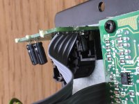
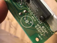
Hopefully these images will clarify the problem somewhat. I think the biggest problem is the disappearance of the copper trace underneath the psu filter cap.
Attachments
-
 EFDEEEC4-2AC0-476A-918A-A6CBE496A5F6.jpg786.7 KB · Views: 127
 -
 A01307A8-F486-4ECD-AD6F-B1E61A79AB29.jpg861.5 KB · Views: 123
 -
 D4551395-BF8D-4539-97F8-1C057BA45B58.jpg606.9 KB · Views: 117
 -
 A12C14C5-2402-4CFC-8D5B-2F355EA1F46E.jpg598.1 KB · Views: 128
 -
 016C6BCE-4778-4C4C-B943-807BAA4B2032.jpg616 KB · Views: 121
Holly macaroni!
Thank you for the schematics, I contacted several divisions and could not get any service manual back.
In regards to the desoldering, the tip was too large / temperature too high or too long applied, which lifted the copper traces from the board.
Thank you for the schematics, I contacted several divisions and could not get any service manual back.
In regards to the desoldering, the tip was too large / temperature too high or too long applied, which lifted the copper traces from the board.
Last edited:
Not sure about that. Temperature was set between 300 and 330 Celsius. My soldering iron is a Monacor SIC 520, which is supposed to a 28W device. The pcb from the other monitor exhibited no problems. I think (hope, actually), that this was just a bad pcb. I've gotten my hands on another set of 4P's, one in good working order, one with an unknown defect. I hope that the good one will have a PCB that will desolder fine, like my first other board. If not, then I'm in trouble. We'll see what a bit of hot glue can do, then...Holly macaroni!
Thank you for the schematics, I contacted several divisions and could not get any service manual back.
In regards to the desoldering, the tip was too large / temperature too high or too long applied, which lifted the copper traces from the board.
Perhaps good or useful to mention is that the legs of the larger elcaps (still only 10mm large) are bent. I don't see how I can bend those legs straight and take the parts out without prolonged heating of the copper pad. I've been looking for desoldering stations, but they are either very expensive, or not being sold. I doubt that it's smart to buy one, for the occasional repair/restoration job that I do.
Any idea on how to best approach this?
Any idea on how to best approach this?
- Status
- This old topic is closed. If you want to reopen this topic, contact a moderator using the "Report Post" button.
- Home
- Amplifiers
- Chip Amps
- Spirit Absolute 4p amp TDA1514A start up pops/clicks