If you want to take the design a further step up its well known that inverting configurations generally give less distortion than non-inverting due to lack of common-mode variations in the input stage. In the inverting config, the -ve and +ve inputs stay at GND potential. The downside of inverting mode is lowish input impedance (not to mention high likelihood of oscillation with no input connection) but that's not a worry for the stage being driven from the X-1 opamp. You probably want to use a second opamp as (non-inverting) input buffer though which feeds the first stage as well as the X-1 opamp.
Last edited:
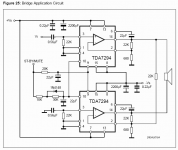
Well.. I am still wondering about a real schematic which were done by someone..
Here:
And YES, I have built it.
Dozens of them, it´s the power section of my 150W 1 x 15" Bass amplifier.
Do not try to make "just one" PCB; buy a ready made one (or a full kit)
Attachments
Here:
And YES, I have built it.
Dozens of them, it´s the power section of my 150W 1 x 15" Bass amplifier.
Do not try to make "just one" PCB; buy a ready made one (or a full kit)
Hey JMFahey. I've just finished wiring it, since it will be actually working as something completely different than audio amplifier (it will amplify uPC generated weaves) - so i needed integrated inside my uPC design (it is just a minor part of it), and therefore a ready board is not an option. Anyway comparing with the original design of the ready ones I believe I have superseded it.

Crossing fingers this referent design to really works.. :|
BTW - why You are saying "Do not try to make "just one" PCB" ? Is there some issues with these PA's ? Something I should be aware of it ?
Last edited:
Happy you (sort of) solved it.
No, my comment means since you are already up your neck with this amp (or you wouldn´t be asking here), adding to it: designing-drawing-burning-etching-drilling a PCB will add unnecessary effort.
To boot, "everything" has a learning curve, so maybe you will be happy only with the 3rd or 4th version.
"Everything" takes at least some debugging so starting with the "datasheet example" is often the safest way.
Including, go figure, important manufacturers who focus on some other aspect and consider the power amp just a generic "black box" which must do its basic job reliably, period.
Happy you (sort of) solved it.
No, my comment means since you are already up your neck with this amp (or you wouldn´t be asking here), adding to it: designing-drawing-burning-etching-drilling a PCB will add unnecessary effort.
To boot, "everything" has a learning curve, so maybe you will be happy only with the 3rd or 4th version.
"Everything" takes at least some debugging so starting with the "datasheet example" is often the safest way.
Including, go figure, important manufacturers who focus on some other aspect and consider the power amp just a generic "black box" which must do its basic job reliably, period.
Well, to be honest I am usually designing digital circuits with quite a lot of components ( like 20-30 IC's ) and so far never had an issue to start working something even this complex from let say 2nd time. Coming to the amplifiers - the analogue stuff - I was stunned that there is some schematics which causing so many problems, and that's why I were asking for something which is tested before.
- Status
- This old topic is closed. If you want to reopen this topic, contact a moderator using the "Report Post" button.