Hi everyone!!
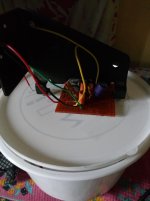
I'm back with yet another wonderful experience playing around with audio amps. Any music lover like me will always be ready to build a Nice and Powerful amplifier whenever they get hold of all the stuffs and ideas. So, I also got an audio chip from my old Onida make crt tv and decided to build another Nice amp for myself. After getting the diagram from datasheet and the components I finally made the amp but when I powered it up from my DIY supply , there was no sound at all!!
I totally broke down into tears. When I closely looked at my circuit , I found that I had accidentally bridged the pins 2 & 3 of the chip while soldering. Pin 2 being the ripple and Pin 3 being the mute pin. So I corrected the mistake and powered it up again with a hope that this time the amp will rock!!
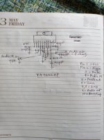
But again to my surprise the amp started making howling noise. So I connected a 4.7 uF capacitor to its Pin 2 (ripple) and ground. But still the amp was making noises. Then I connected a 2.2 ohm resistor with the 0.1uF capacitor at its output pin and ground hoping that this may resolve the issue. But again I became frustrated with the noise. So, Finally I connected a 220 ohm resistor and 47 uF capacitor between pin 5 (feedback) and ground hoping that this may be the cause of noise and howling due to excessive gain. This time I was correct and amp started making nice, clean and powerful sound!!")
So, conclusion is that datasheets are always not correct but may be misleading to new Tinkerers :-|
I'm back with yet another wonderful experience playing around with audio amps. Any music lover like me will always be ready to build a Nice and Powerful amplifier whenever they get hold of all the stuffs and ideas. So, I also got an audio chip from my old Onida make crt tv and decided to build another Nice amp for myself. After getting the diagram from datasheet and the components I finally made the amp but when I powered it up from my DIY supply , there was no sound at all!!
I totally broke down into tears. When I closely looked at my circuit , I found that I had accidentally bridged the pins 2 & 3 of the chip while soldering. Pin 2 being the ripple and Pin 3 being the mute pin. So I corrected the mistake and powered it up again with a hope that this time the amp will rock!!
But again to my surprise the amp started making howling noise. So I connected a 4.7 uF capacitor to its Pin 2 (ripple) and ground. But still the amp was making noises. Then I connected a 2.2 ohm resistor with the 0.1uF capacitor at its output pin and ground hoping that this may resolve the issue. But again I became frustrated with the noise. So, Finally I connected a 220 ohm resistor and 47 uF capacitor between pin 5 (feedback) and ground hoping that this may be the cause of noise and howling due to excessive gain. This time I was correct and amp started making nice, clean and powerful sound!!
So, conclusion is that datasheets are always not correct but may be misleading to new Tinkerers :-|
Attachments
Last edited: