Hey folks,
I just finished a long term project - building a Chip-Amp with the LM3886. Its a 6-Channel Amp, so 3x Stereo (for now only sub and fullrange driven - later then also tweeters)
The thing here is, I did't use isolators between the cooling blocks and the Chips - but knowingly that the -V power supply is connected to the body of the LM3886 I separated the blocks. So every chipamp has it's own aluminum cooling block with no connection to the ground.
I ordered 0.0035" thin mica pces - but still worrying to use them, because the heatsinks feel pretty hot - and with them the heat would be transferred even worse.
So question here: If the heatsink itself is isolatet but the chip to the sink is not, do I have to worry about any negative sideeffects? So far it works pretty well!
Thanks in advance!
Michael
+1 for thermal pads and goop.
If your heat sinks get hot, it's likely because they're under-sized. If you run the LM3886 at ±28 V, you can expect each LM3886 to dissipate 40 W when operated at clipping with a sine wave signal into a 4 Ω load. If you then run three LM3886es per heat sink, they'll certainly get hot.
I go through the thermal design around the LM3886 here: LM3886 chip power amplifier thermal design.
You may find it insightful.
Tom
Thanks for the answers!
Here are two pics of the thing.
The heatsinks are about 3x6x8cm for each chip a single one.. and they're finely finned not massive, alu..
And - yeaah I underestimated the trafos my PSU (only snubberized - no chips) drive 34V +/- which is close to the edge.
And yeaah another "unprofessional" choice: I use a wooden housing (no problems with cellphone or radio signals so far - and it looks damn good )
)
so no problems with connection to the ground. The 34 Volts stay there safely.
Michael
Here are two pics of the thing.
The heatsinks are about 3x6x8cm for each chip a single one.. and they're finely finned not massive, alu..
And - yeaah I underestimated the trafos my PSU (only snubberized - no chips) drive 34V +/- which is close to the edge.
And yeaah another "unprofessional" choice: I use a wooden housing (no problems with cellphone or radio signals so far - and it looks damn good
)so no problems with connection to the ground. The 34 Volts stay there safely.
Michael
Attachments
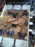
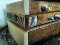
Yeah. Those heat sinks are designed for forced air flow. By boxing them in like that and by having the fins horizontal, you're not giving them a chance to work. They will get hot.
You don't need a regulated power supply for the LM3886. A regular transformer+rectifier+caps (snubber or no snubber) will work just fine.
Tom
You don't need a regulated power supply for the LM3886. A regular transformer+rectifier+caps (snubber or no snubber) will work just fine.
Tom
A pair of little fans screwed at the back of your box would go a long way to keep the heatsinks cooler. Some fans are really very silent these days.
And yes, isolate your heatsinks. They're too exposed, you'll end up shorting them to gnd one way or another (Murphy's law will take care of that).
And yes, isolate your heatsinks. They're too exposed, you'll end up shorting them to gnd one way or another (Murphy's law will take care of that).
Yes it's true that the fins are designed for airflow - but the principle of "surface area enlargement" should also do its part. - and horizontal or not they are exposed to the outside.
I think - if not just living with that state - lowering the voltage would be chance.
Is there an easy way - without exchanging the the whole toroids? (lowering R1 e.g.?)

I think - if not just living with that state - lowering the voltage would be chance.
Is there an easy way - without exchanging the the whole toroids? (lowering R1 e.g.?)
Lm3886 became famous because gaincard amplifier 3000$ was using it (3875) . It functions at very high temperature as the outputs are not ordinary 150C° ones but 250C° and protected . The datasheet gives the smallest heat sink to be used . As long as the temperature of the heatsinks don't exceed 70C° you don't need to bother about.
As you chose nonisolated version you can get advantage of the case and power the negative not by pin 4 but from the heat sink . Apply the negative lead of the bulk capacitor directly to the screw by round terminal. The positive pin 1 can be enforced by soldering the bulk capacitors lead up to the root from external edge of the IC and solder the incoming +V to the capacitors lead.
To enhance the sound , try lower gain , down to 2.8 by 180 ohm 1w feedback resistor and 100 ohm ½W shunt resistor grounding without capacitor. It is perfectly stable , compare the sound with others , if you prefer it than either amplify the input signal by a driver high quality op amp as AD826 or apply a step up transformer as I do 600/10k .
I think the only disaster that could happen is a chip burning for 5$ - ok the speakers would be financially critial (and I already lost one...)
And no 34V you just do not feel - even with wet hands and no shoes.
@kokoriantz
Ok I see what you are trying to tell me here: lower the gain of the final stage and giving more power with my preampstage!? I already use a pair of AD826 to drive my crossover and filter network - but several notchfilters lower the signal voltage noticeable. I still have a pair of LT1028s and a coolable LME49720(TO) at Home to build preampstages that could come after the crossover for the two channels... maybe I'll give it a try, thanks!
And yes I drive the LM3886s at a remarkably high gain (10k and 680R).
So you say high supplyvoltage AND high gain are an ill match!?
And I will remove the caps that ground the signal path in the middlepieces - only used them as an attempt to kill noise that eventually came from a bad grounding (loops - caps too far - PSU too close etc..) -which is now stable.
What I don't get: why using the sinks as powerinput? doesn't make a difference does it?
Last edited:
I think the only disaster that could happen is a chip burning for 5$ - ok the speakers would be financially critial (and I already lost one...)
And no 34V you just do not feel - even with wet hands and no shoes.
@kokoriantz
Ok I see what you are trying to tell me here: lower the gain of the final stage and giving more power with my preampstage!? I already use a pair of AD826 to drive my crossover and filter network - but several notchfilters lower the signal voltage noticeable. I still have a pair of LT1028s and a coolable LME49720(TO) at Home to build preampstages that could come after the crossover for the two channels... maybe I'll give it a try, thanks!
And yes I drive the LM3886s at a remarkably high gain (10k and 680R).
So you say high supplyvoltage AND high gain are an ill match!?
And I will remove the caps that ground the signal path in the middlepieces - only used them as an attempt to kill noise that eventually came from a bad grounding (loops - caps too far - PSU too close etc..) -which is now stable.
What I don't get: why using the sinks as powerinput? doesn't make a difference does it?[/QUOTe
It is your amp. If mine the LM3886 would have mica insulators, proper shoulder washers, and thermal paste. Then all the individual heat sinks would be be connected electrically and grounded.
I will take your word on touching the heat sinks with wet hands and feet.
What I don't get: why using the sinks as powerinput? doesn't make a difference does it?
The die in most ICs is connected to the lowest voltage in the circuit. In this case, that's VEE. To get low thermal resistance between the metal back of the package (the die attach paddle or DAP), the chip is likely soldered to the DAP. That creates an electrical connection. It's up to the end user to isolate the package electrically from the heat sink.
Tom
- Status
- This old topic is closed. If you want to reopen this topic, contact a moderator using the "Report Post" button.
- Home
- Amplifiers
- Chip Amps
- LM3886*T* without mica foil - working!(?)