Hi guys,
So I've settled on building my first GainClone (and first amp ever btw) and will be using circuitbasics' design for the amplification part and Decibel Dungeon article for PSU design.
I'm more and more confident in grasping the overall concept (splitting the different parts of the amp part in their functional use was a big help, see image below), although I still have a few questions in mind, most of same coming from the fact that on most of the resources I can find, PSUs & amp part are treated separately, leading to some confusion for the newbie I am
Please keep in mind that although I am familiar with invidual component usage (memories from engineering school help), I'm still learning about their application in diy audio.
Here are my designs (better writing writing them down to understand them):
PSU
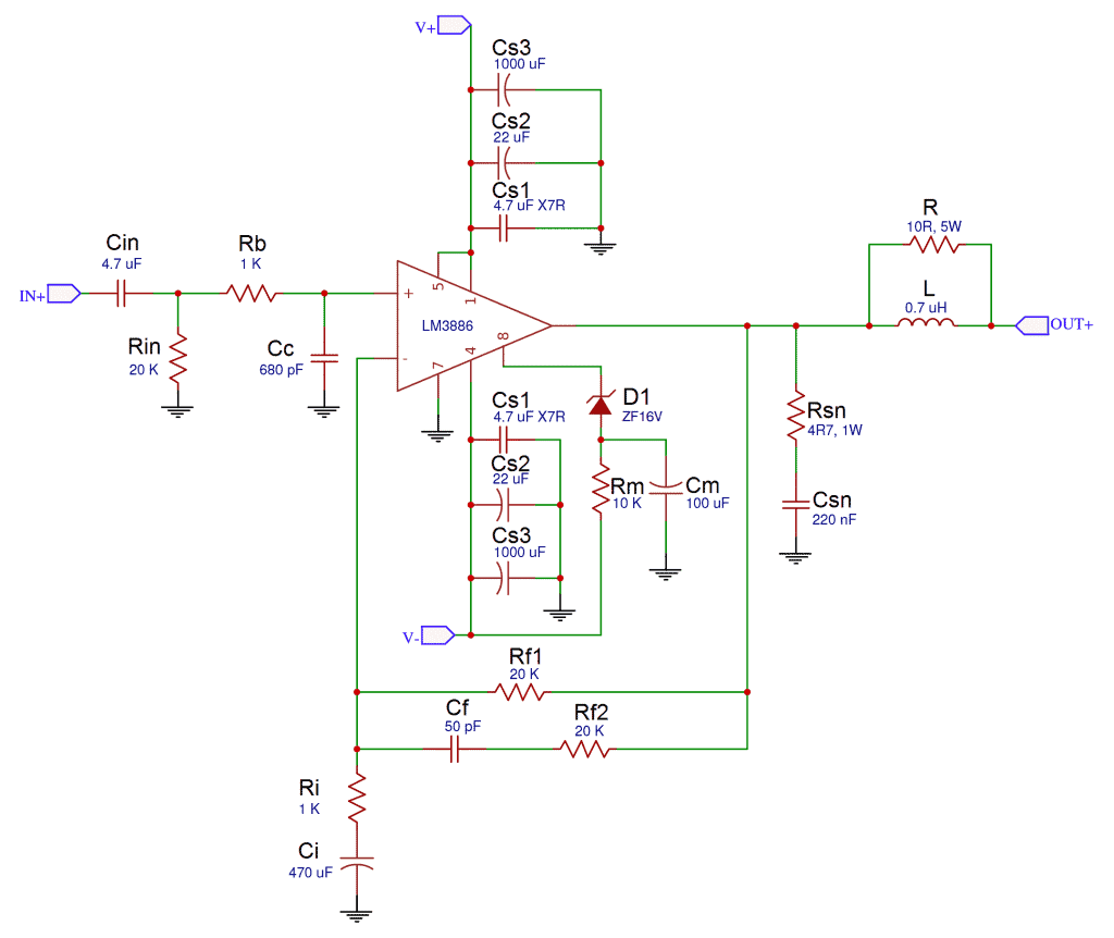
Amplification
Questions :

So I've settled on building my first GainClone (and first amp ever btw) and will be using circuitbasics' design for the amplification part and Decibel Dungeon article for PSU design.
I'm more and more confident in grasping the overall concept (splitting the different parts of the amp part in their functional use was a big help, see image below), although I still have a few questions in mind, most of same coming from the fact that on most of the resources I can find, PSUs & amp part are treated separately, leading to some confusion for the newbie I am
Please keep in mind that although I am familiar with invidual component usage (memories from engineering school help), I'm still learning about their application in diy audio.
Here are my designs (better writing writing them down to understand them):
PSU
An externally hosted image should be here but it was not working when we last tested it.
Amplification
An externally hosted image should be here but it was not working when we last tested it.
Questions :
- I'm sticking to a one transformer design to keep components costs low ; will a 160VA 2x24V 3.33A toroid transformer be enough ? Can you confirm that both channel's V+ (alternatively V-) are connected (as in my sketches ?)
- PCD vs. breadboard ? I was thinking about making the rectifier bridges with breadboard and using premade PCB for the amp section (I can imagining my nightmare already trying to connect everything on a breadboard there...)
- Would you advise some PCBs in particular (leading to a overall change in the design, sigh...) ? I see in the forum lots of chipamp PCBs, but the website doesn't seem to exist anymore...)
- Grounds : oh boy, this part might be the most confusing for me. I'm struggling to actually connect the PSU & amp parts. I read an article in the forum that in the end, PWR_GRND & SIG_GRND (the output signal ground right?) should be connected, but what about the Audio IN ground ? Should all these grounds be connected to the rectifier bridges common ground ? My confusion actually comes from the fact that CircuitBasics article provides two version of the design, one with what seems to be a common ground (first image below) and the second one with separated grounds (second below)
- I'd like to add a potentiometer to the design ; from a few design I read online, I see that it's supposed to be right after Audio IN, and connected the ground (depending on the answer to the previous question). But I'd like to have only one potentiometer for both channel. How can I manage that ? (edit : or would you advise to stick to a no-pot design, driving the volume from the input ?)
Last edited:
You can check this out:
Ground Loops
There are two pdf files there, "How to Wire up an Audio Amplifier" is very detailed and I guess that circuitbasics guy got his "Main System Ground" idea from here. Other one, "More Guidelines for Minimizing Amplifier Hum" is shorter and I implemented his pcb star ground on page 3 on my gainclone and it's very silent, has no hum or interference.
- Status
- This old topic is closed. If you want to reopen this topic, contact a moderator using the "Report Post" button.