Hi,
I'm new to the forum.
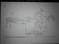
Please find see the attached schematic of my effort to reproduce the Cordell Super Gainclone using the LM4780 as opposed to the LM3886.
I have simulated the circuit in Proteus with some success and plan to see if it works in reality. Probably due to my lack of knowledge, the current mute circuit works in reverse, open circuit gives amplification. The output initially went rail to rail with SW1 circuit closed. Installing output caps C22 and C23 seems to have fixed that but I'm still unsure as to why.
I know it is probably futile to try to simulate the circuit as reality is always very different. I did this because it helps me to prevent catastrophic failure and wasted time.
I am not an electronics expert, and realise there are probably many errors in the circuit, therefore, I was hoping for any criticisms prior to embarking on silk-screening a pcb. I believe I need to separate the signal grounds from the power grounds.
Any input is more than welcomed.
I'm new to the forum.
Please find see the attached schematic of my effort to reproduce the Cordell Super Gainclone using the LM4780 as opposed to the LM3886.
I have simulated the circuit in Proteus with some success and plan to see if it works in reality. Probably due to my lack of knowledge, the current mute circuit works in reverse, open circuit gives amplification. The output initially went rail to rail with SW1 circuit closed. Installing output caps C22 and C23 seems to have fixed that but I'm still unsure as to why.
I know it is probably futile to try to simulate the circuit as reality is always very different. I did this because it helps me to prevent catastrophic failure and wasted time.
I am not an electronics expert, and realise there are probably many errors in the circuit, therefore, I was hoping for any criticisms prior to embarking on silk-screening a pcb. I believe I need to separate the signal grounds from the power grounds.
Any input is more than welcomed.
Attachments
...Any input is more than welcomed.
Don't the "+IN" pins need a DC reference?
Pretty sure they do.
Attachments
Thanks PRR.
Could you give me a hint on how to implement that? Would that be like a high value, say 47k, resistor going to the signal ground?
Could you give me a hint on how to implement that? Would that be like a high value, say 47k, resistor going to the signal ground?
Look at the schematic on page 540 of Bob's book.
It's meant to be connected to the quiet ground. Pin 5 of U1:B and U4:B are also meant to be connected to the quiet ground.
I don't think the development of the Super Gain Clone was ever completed? Do you have access a Cordell PCB layout?
It might be easier to build one of composite amplifiers discussed and marketed on this forum. (My_Ref Fremen Edition and/or Modulus-86/286) Then at least you can get a decent PCB as a starting point, proven design, build instructions and plenty of support if things go wrong.
Regards ...
Thanks PRR.
Could you give me a hint on how to implement that?
It's meant to be connected to the quiet ground. Pin 5 of U1:B and U4:B are also meant to be connected to the quiet ground.
I don't think the development of the Super Gain Clone was ever completed? Do you have access a Cordell PCB layout?
It might be easier to build one of composite amplifiers discussed and marketed on this forum. (My_Ref Fremen Edition and/or Modulus-86/286) Then at least you can get a decent PCB as a starting point, proven design, build instructions and plenty of support if things go wrong.
Regards ...
Last edited:
Bob showcased the Super GC at the NJ Audio Society and it sounded fantastic.
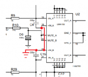
Pins 16 and 22, IN+A and IN+B should be grounded.
Pins 16 and 22, IN+A and IN+B should be grounded.
About the earthing?
Are you suggesting a single common ground? Bob's schematic has a quiet ground and a circuit ground. Quiet ground is connected to circuit ground via a 4.7 ohm resistor.
Thats good to hear it progressed. I assume the schematic is the same as documented in his book? Was it using the Klever Klipper?Bob showcased the Super GC at the NJ Audio Society and it sounded fantastic.
Pins 16 and 22, IN+A and IN+B should be grounded.
Are you suggesting a single common ground? Bob's schematic has a quiet ground and a circuit ground. Quiet ground is connected to circuit ground via a 4.7 ohm resistor.
Many thanks for the kind input.
I really don't want to build an amp from a premade board, instead, I like to simulate in Proteus and tinker and fiddle with what comes out using the oscilloscope and listen to the audio out.
No I don't have a Cordell PCB, I'll get a silkscreen made, diy the PCB with ferric chloride using the most basic of principles, using other boards for reference only regarding layout.
I tried the Myref amp in Proteus but most probably due to my lack of knowledge, it would go bananas at every opportunity, so I won't even attempt a build despite the fantastic reputation of the amp (RIP Mauro and sorry I couldn't do you justice).
Regarding the quiet 4.7 Ohm resistor, everything works great except the Mute switch, which previously worked in the oposite sense. With 4.7 Ohms, the amp will not mute. With any resistor smaller than 10M, either the amp stays unmuted or gives a strange square wave or similar. I need to research the math on the datasheet more. I'm not sure if this has anything to do with the inverted configuration of the amp. I've used the mute on a standard non-inverted GC in Proteus with no reverse mute operation, so know the simulation model works.
I've attached the DC Servo page from the Cordell schematic.
Attachments
FWIW, the proteus model is probably cobbled together from the schematic of the LM3886. Texas Instruments does have a working model for the LM3886 but it is encrypted and difficult to find ever since their Overture Series chips were re-branded and the single chip amplifiers EOL.
Yes that is quite correct. The schematic I posted would look exactly like two 3886's if the child circuit was visible.
I have made the Quiet Grounds, please see the updated diag. I hope they are now correct.
Are there any other signal ground points that should go to the Quiet Ground?
The amp refuses to mute in this configuration!
jackinnj, I've included the child diagram with the two 3886's shown. I wanted to use the 4780 and use it's package hence the use of the 3886's!
Are there any other signal ground points that should go to the Quiet Ground?
The amp refuses to mute in this configuration!
jackinnj, I've included the child diagram with the two 3886's shown. I wanted to use the 4780 and use it's package hence the use of the 3886's!
Some power supply suggestions -- place 100nF ceramic and 10uF electrolytics as close to the V+/- pins of the LM4780 as possible. Bridge the V+/- pins with a 100nF film cap.
The OPA2604's can be run "hot" --
The OPA2604's can be run "hot" --
Where is the latest version of your schematic?
Tom (neurochome.com) had an amp very similar to this, parallel86.
Tom (neurochome.com) had an amp very similar to this, parallel86.
Latest attached with 100n caps and klever Klipper, which works like a charm!
The only problem I still have, is the Mute function. It does not Mute! I suspect the model, as it works as advertised in non-invert config.
The amp (in Proteus) is incredibly stable compared to others I've simmed.
The only problem I still have, is the Mute function. It does not Mute! I suspect the model, as it works as advertised in non-invert config.
The amp (in Proteus) is incredibly stable compared to others I've simmed.
Attachments
The model is probably the one that TI made available a few years back where the mute input is inverted. What you have drawn should work.
The challenge here is going to be designing a layout. Sometimes less is more.
The challenge here is going to be designing a layout. Sometimes less is more.
Yeah Mark I get the picture "Less is more"! I included the Klever Klipper to see the results of excessive input voltage. It is really good at its job. Careful control with a dual volume input pot should obviate the need for the Klipper. The use of the 4780 was the initial challenge but I do realise the benefits of having two completely separate channels and going down the 3886 route. I'll see how it goes. Worst case scenario will be to use the LM3886 and do two monos.
Regarding the LM3886 model, it works correctly in a non-inverted circuit!
Regarding the LM3886 model, it works correctly in a non-inverted circuit!
- Home
- Amplifiers
- Chip Amps
- Gainclone using the LM4780 based on Cordell