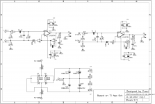
I would remove C11-C14 since they only bring the diodes ringing frequency down but do not eliminate it. You need a true CRC snubber at the AC side to cope with such ringing. Also why do you insist on having fuses in DC rails? It was already mentioned that it does more harm than good in this position. It will almost certainly fry woofers of both channels if one fuse goes off while the other is conducting and this is very likely situation for a beginner for whom you intend this project. Why don't you move the fuses to the AC side before the diodes? This will keep speakers safe in case if one fuse goes off and still provide the same level of protection in case of catastrophic failure. The PCB area is the same, so there should not be a problem here.
Regards,
Oleg
1. C11-14: Better to have pads as an option, isnt it?.
2. CRC snubber+quasimodo optimization: Out of scope of this small beginner level project.
3. Why do you think the fuse will blow on its own without anything catastrophic happening downstream?... Can you let me know the situation where it might happen?
one can atleast put a big value series cap (cap bank) for speaker protection. This is also beneficial in rolling off bass that cant be handled by the speaker (if its a small speaker or full range driver). If not, atleast implement simple speaker protection unit amply available on ebay and likes.
I getting a lot of negative vibes here... may be I will drop the thing.
1. These pads are just useless.
2. Is not really necessary. I doubt many could tell if they hear any difference with or without CRC snubber. At least I haven't seen such reports on this forum.
3. Situation is simple - one rail is overloaded for whatever reason, either due to DM probe slipped while measuring things or output transient into the real speaker is too high or any other scenario you are aiming to protect against by using the fuses. Once this happens the fuse in this rail blows and instead of protecting things it takes with it both channels' woofers because the other rail is still there and thus the IC most definitely pulls its output to a full rail DC voltage. While if you just rearrange the fuses and diodes order (fuses go before the diodes on AC side) even if only one fuse blows it will result in increased PSU ripple and lower PSU output voltage but will not put DC on the amps output. If both fuses blow then the amp is safe for the speakers as well. Also if fuses are put on the AC side chances are high that both fuses will blow simultaneously since if one blows the other will have to pass double the initial fault current and thus will blow too.
Apart from the points above I think the board is good for a beginner project. And you do not have to drop it just because someone is trying to help you improving your design")
2. Is not really necessary. I doubt many could tell if they hear any difference with or without CRC snubber. At least I haven't seen such reports on this forum.
3. Situation is simple - one rail is overloaded for whatever reason, either due to DM probe slipped while measuring things or output transient into the real speaker is too high or any other scenario you are aiming to protect against by using the fuses. Once this happens the fuse in this rail blows and instead of protecting things it takes with it both channels' woofers because the other rail is still there and thus the IC most definitely pulls its output to a full rail DC voltage. While if you just rearrange the fuses and diodes order (fuses go before the diodes on AC side) even if only one fuse blows it will result in increased PSU ripple and lower PSU output voltage but will not put DC on the amps output. If both fuses blow then the amp is safe for the speakers as well. Also if fuses are put on the AC side chances are high that both fuses will blow simultaneously since if one blows the other will have to pass double the initial fault current and thus will blow too.
Apart from the points above I think the board is good for a beginner project. And you do not have to drop it just because someone is trying to help you improving your design
You mean a compact PCB design?compact lm1875 circuit
If so, to widen your possibilities also search for TDA2030 and 2050 board designs, they are all pin compatible and designs can be freely interchanged.
Circuits are basically compatible too, just use them with datasheet approved supply voltages and loads.
hi,
I was looking for a compact lm1875 circuit. You found it on the supply circuit. Can you share the files?
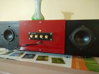
My LM1875 has been in service in a the Paul Carmody's "Sprite" boombox for about 3-4 years now and working flawlessly. it uses a tone control from ali express, but really never really felt the need to adjust bass. It has plenty of low end for the small kitchen where wife uses it.
Attachments
- Home
- Amplifiers
- Chip Amps
- LM1875 Stereo Amplifier with integrated PSU