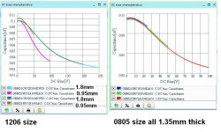
Murata's plots are typical of Hi K ceramic.
X7R perform quite a bit better and when used on a near constant DC supply voltage have near zero capacitance change. eg a 220nF 50V cap on a 35V supply might have an installed capacitance of 170nF, but stays near that value because the DC stays near it's normal operating value.
For audio passing capacitors one can use the Lo K Class1 ceramics designated NP0/C0G both for filtering duty and/or for coupling duty.
Now that MLCC are available you can get higher NP0/C0G values that were rarely seen 10years ago.
are you sure.
Now that MLCC are available you can get higher NP0/C0G values that were rarely seen 10years ago.
remember the OP wants >1uF range
So the OP needs 2 of them at 4 Euros a pieceThe biggest value NP0/C0G SMD cap that is available from mouser is 0.47uF. It is 2220 size which means that the board area would be smaller if 5mm leads pitch polyester film cap is used instead.
Any manufacturing engineer would be hung if he dared specifying 2 of those,
but hey this audio.
In modern SMD mobile phones they use solid tantalum here for audio / headsets.
X7R and X5R are well known for their capacitance vs voltage characteristics.
so it is important that the voltage across the cap does NOT change, to have a stable capacitance, and reduce modulation of series impedance with momentary voltage. (distortion). so first is to determine wether the voltage changes, and that is only at low frequencies (coupling) or when used in filters. this means you can safely use these ceramics in coupling stages, but not use them as high pass filters. so overrate the value at least 10x (or HP freqs < 1hz), plus some marging for the curve if there is a large dc difference across the cap.
so it is important that the voltage across the cap does NOT change, to have a stable capacitance, and reduce modulation of series impedance with momentary voltage. (distortion). so first is to determine wether the voltage changes, and that is only at low frequencies (coupling) or when used in filters. this means you can safely use these ceramics in coupling stages, but not use them as high pass filters. so overrate the value at least 10x (or HP freqs < 1hz), plus some marging for the curve if there is a large dc difference across the cap.
- Status
- This old topic is closed. If you want to reopen this topic, contact a moderator using the "Report Post" button.
- Home
- Amplifiers
- Chip Amps
- Ceramic Capacitor for audio input