pencil and paper is good enough. You can use coloured crayons if you feel colour will help differentiate some of the cable/connection types.OK, will try to draw it. My computer drawing skills suck though. I'll post a photo of a drawing.
Post a pic of the drawing.
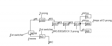
Oh, so many ground loops, so little time... ") If you run XLR to the MOD86, you shouldn't have issues with ground loops, though. Unless they somehow get into the signal path prior to the MOD86.
If you run XLR to the MOD86, you shouldn't have issues with ground loops, though. Unless they somehow get into the signal path prior to the MOD86.
I take by AES you mean a coax connection? Do you have a way to make that an optical link? That would eliminate 90 % of the ground loops - or at least move them away from the amplifiers.
Tom
If you run XLR to the MOD86, you shouldn't have issues with ground loops, though. Unless they somehow get into the signal path prior to the MOD86.I take by AES you mean a coax connection? Do you have a way to make that an optical link? That would eliminate 90 % of the ground loops - or at least move them away from the amplifiers.
Tom
AES is an XLR connexion. There are optical inputs/outputs on the DEQ. I will try them.
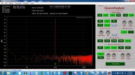
For your viewing pleasure, I took two screen shots of the left and right channels via the QA400 distortion analyzer, using a resistor ladder on the outputs so as to limit the voltage seen by the QA400.
Ignore the selection of Right channel on both control panels. The analyzer connections used the Right channel I/O for both channels of the Modulus86.
The THD figures are 0.00104% and 0.00118%, with THD+noise being 0.00440% and 0.00425% respectively. To me, that says the build is fine.
Attachments

Last edited:
I think you're pushing the dynamic range of the QA400. Run the MOD86 at full output power and divide the output voltage to the highest the QA400 can tolerate. That's the best you can do. If you can't get the harmonics to show above the noise floor, you're limited by the measurement gear.
Is there a way to increase the FFT length so you can get higher frequency resolution? And higher averaging so you can get the noise floor down a bit? I typically run with 512k points and 16-32 averages.
I do agree with your fundamental assessment, though. You have a mighty fine build there. Thanks for sharing.
Tom
One TOSlink cable between the DEQ and the SRC and the noise problems are solved.
Thanks for the suggestion.
Could probably delete the ground loop isolator now too... using a switch is a really good idea to future proof the item.
EDIT: Thanks for the compliment. Your boards made this pretty straightforward. Given the noise floor is swamping the harmonics, it looks very much like the distortion can even be lowered.
To run at full output, I will need to build a big resistor box to provide an 8 ohm load. I should do that anyway, since this is not going to be the last amp I work on.
Last edited:
One TOSlink cable between the DEQ and the SRC and the noise problems are solved.
Thanks for the suggestion.
Awesome. Glad to help.
Could probably delete the ground loop isolator now too... using a switch is a really good idea to future proof the item.
That's certainly worth a try.
To run at full output, I will need to build a big resistor box to provide an 8 ohm load. I should do that anyway, since this is not going to be the last amp I work on.
+1
Nearly a decade ago I picked up a bunch of Vishay-Dale RH-25 25 W non-inductive resistors. I found 20 of them on eBay for not that much money. 0.8 ohm each. Perfect for building an 8 ohm dummy load with a 4 ohm tap in the middle. Put the two halves in parallel for 2 ohm.
I have them mounted on a heat sink that came from a cell phone base station (also an ebay find). The heat sink has two fans on it, temperature controlled with an NTC resistor. Works great. I think the entire rig set me back, maybe, $50 plus a few hours of drilling and tapping holes.
I routinely dissipate 100-200 W into that thing. With the fan, the resistors stay lukewarm, but my lab sure gets toasty... Nothing beats a space heater with 0.00014 % THD
Tom
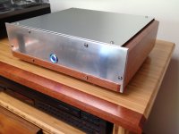
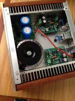
Here is my finished unit. This was my first attempt at building an enclosure from scratch and the umm, "learning process" dragged out for the better part of two months as I explored the unique challenges of combining wood and metal when one only owns wood tools. Wanted wood to reference some vintage gear in the house plus match my existing lacewood/bamboo shelving unit.
A few brief thoughts and impressions:
Tom's documentation and support are excellent. Highly recommended project.
The amp is very clean and precise. I have run it with several input and speaker combinations and it sounds great with all of them - very enjoyable.
21 cm is not quite wide enough in this layout if one wants a front mounted mains switch. 22 cm would have eliminated a number of headaches in final wiring. (borrowed Friendly Dominique's idea of a false bottom to stash my mains and tranny wiring in between two bottom panels to gain just enough room to fit the push button switch)
Furniture grade joinery between wood and metal is a major pain!
It does not get even faintly warm and is completely over heat managed with big heat sinks and nifty (unnecessary) passive convection channels that ventilate the internals.
Thanks for the wonderful product Tom, and thanks to others here from whom I have learned quite a bit.
Attachments
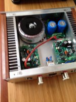
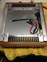
Love the built, what kind of power switch is that?
Ha, ha funny to ask that, the switch was my personal hell (x4)
First one had intermittent defect
Second I damaged trying to fit in too tight space
Third lost in shipping
Fourth from different vendor required enlarging hole in front panel
Search terms will be " latching illuminated pushbutton switch"
Popular in automotive, 12v LED and most 250v/2 or 3A rated
Very happy with this one from eBay, bigger solder tabs and much more robust:
19mm 12V Blue LED Light Self Locking Latching Car Push Button SPDT Switch Off On | eBay
It's called South American Lacewood, and you are correct, used leftover pieces from the stereo cabinet project for amp sides.
A side note, the stuff is dense enough that it accepted undersized drilled and tapped M4 machine threads in the end grain butt joints. Used 20mm long bolts and assembled/disassembled multiple times with no stripping of threads.
A side note, the stuff is dense enough that it accepted undersized drilled and tapped M4 machine threads in the end grain butt joints. Used 20mm long bolts and assembled/disassembled multiple times with no stripping of threads.
What is the input impedance of the Modulus-86 rev.1 ? I was wondering if the relatively high 560 Ohm output impedance of a miniDSP unit I would want to drive it with would be a satisfactory match.
Thanks, /path
Did you get a miniDSP running with Modulus 86? I'm thinking of doing the same. Wondering if you like them together.
AlexQS
A side note, the stuff is dense enough that it accepted undersized drilled and tapped M4 machine threads in the end grain butt joints. Used 20mm long bolts and assembled/disassembled multiple times with no stripping of threads.
Damn... That's pretty impressive.
Tom
- Home
- Amplifiers
- Chip Amps
- Modulus-86 build thread