4xLM3886 fuse blow-out
what wrong with this schematic?
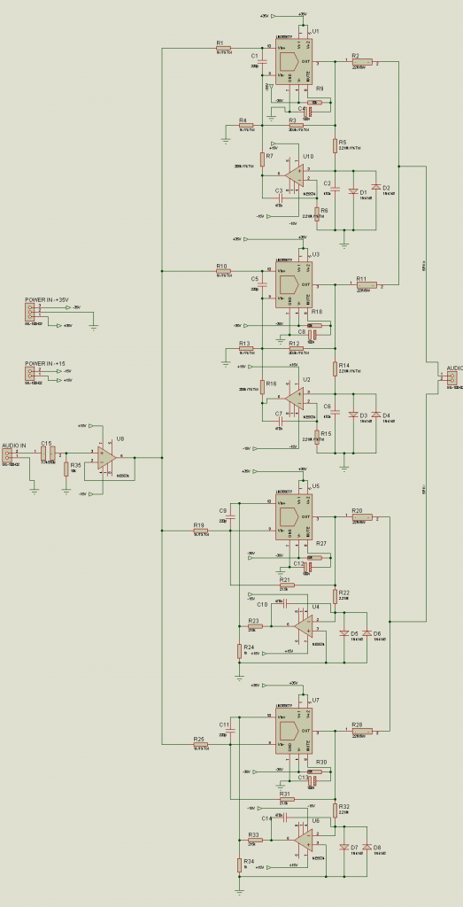
I found this diagram to this forum site:
w w w .elab.ph/forum/index.php?topic=45229.40
the thread starter also put a link for pcb
w w w .4shared.com/file/yMDRO11oce/bpa200.html
I follow everything but I guess there is something wrong.
I recheck the pcb and I'm 100% sure that there's no shorted traces.
I put 5A fuse and it's always blow in a negative side of the rail.
what wrong with this schematic?
I found this diagram to this forum site:
w w w .elab.ph/forum/index.php?topic=45229.40
the thread starter also put a link for pcb
w w w .4shared.com/file/yMDRO11oce/bpa200.html
I follow everything but I guess there is something wrong.
I recheck the pcb and I'm 100% sure that there's no shorted traces.
I put 5A fuse and it's always blow in a negative side of the rail.
Last edited:
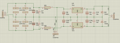
I don't see anything wrong with the schematic but the power supply isn't shown?
That file sharing site is annoying and i'm not going to log into it to download the pcb info.
Double check that you installed all parts correctly.
See if the psu alone blows the fuse with just a dummy load.
That file sharing site is annoying and i'm not going to log into it to download the pcb info.
Double check that you installed all parts correctly.
See if the psu alone blows the fuse with just a dummy load.
Is this another Member that does not understand how a SINGLE chipamp operates and yet he/she jumps headlong into a multi-chipamp implementation?
Why call it a 4x3886 when National's name for it is BPA200?
Why call it a 4x3886 when National's name for it is BPA200?
The +15V/ -15V have no reference to ground as shown on the schematic ? If you are going to run the OpAmps with a single voltage of 30V, you are going to need to bias the OpAmps with additional parts and use AC coupling capacitors ?
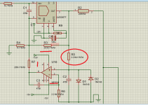
Try to remove components C4,C8,... in order to deactivate the Mute function. During the muting the servo loop is broken and the outputs of opamps can rich opposite voltages to force current between LM3886 after stepping out from mute mode.
It's better to not apply the delayed muting in case of parallel tied setup, because the timing can be an issue between chips:
https://docs.google.com/file/d/0BzbIeQI27LjoV21seUw4MG5jQWs/edit
On the other hand the resistors seem to be too high value around the NE5534s otherwise use JFET input opamp or bipolar type with bias current cancellation.
The +15V/ -15V have no reference to ground as shown on the schematic ? If you are going to run the OpAmps with a single voltage of 30V, you are going to need to bias the OpAmps with additional parts and use AC coupling capacitors ?
The power supply ground is on J2.
I question the need for the DC servo circuitry at all, the offset of the 5534 with a 2.2M input resistor is going to be a lot worse than the LM3886. The 5534 is not unity gain stable and probably needs to be compensated for integrator use. If you want to use the servo choose a low offset fet input unity gain stable op-amp instead. (It does not need to be fast)
Try to remove components C4,C8,... in order to deactivate the Mute function. During the muting the servo loop is broken and the outputs of opamps can rich opposite voltages to force current between LM3886 after stepping out from mute mode.
It's better to not apply the delayed muting in case of parallel tied setup, because the timing can be an issue between chips:
https://docs.google.com/file/d/0BzbIeQI27LjoV21seUw4MG5jQWs/edit
On the other hand the resistors seem to be too high value around the NE5534s otherwise use JFET input opamp or bipolar type with bias current cancellation.
do you mean sir I try to remove all mute caps c4,C8,c12,c13.
I have also doubt with the NE5534s
The power supply ground is on J2.
I question the need for the DC servo circuitry at all, the offset of the 5534 with a 2.2M input resistor is going to be a lot worse than the LM3886. The 5534 is not unity gain stable and probably needs to be compensated for integrator use. If you want to use the servo choose a low offset fet input unity gain stable op-amp instead. (It does not need to be fast)
thanks to all response...
try to test again, I remove the ne5534 and the fuse dosn't blow-out but there's an a "zzzz...." sound on the board. and also base on the data-sheet of ne5534, 5534 is Fast opamp NE5534 10mhz than opa134 8mhz. the problem is opa134 is not available in the Philippines.
any good substitute?
TL071 also blow-out after a few seconds, please help...
can somebody give me a copy of bpa-200 better than to my schematic I posted. Please
can somebody give me a copy of bpa-200 better than to my schematic I posted. Please
TL071 also blow-out after a few seconds, please help...
can somebody give me a copy of bpa-200 better than to my schematic I posted. Please
can somebody give me a copy of bpa-200 better than to my schematic I posted. Please
thank you How can I modified the schematic using TL071 in DC Servo.
I asking because the only available low offset opamp in the Philippines is TL071.
Please help.
the schematic I follow came from other forum is wasting my money and time.
Last edited:
PA150 Trimmer
Hi
I have a unsuccessful making the BPA200 using the attachment Diagram ( bpa200 diagram).
I want to try another project from shine7 PA150 which is part of bpa300.
I have some question:
Q1: What is the purpose of R4 in PA150?
Q2: can I change it to fix resistor? and what is the good value?
thanks
Hi
I have a unsuccessful making the BPA200 using the attachment Diagram ( bpa200 diagram).
I want to try another project from shine7 PA150 which is part of bpa300.
I have some question:
Q1: What is the purpose of R4 in PA150?
Q2: can I change it to fix resistor? and what is the good value?
thanks
Attachments
The resistor is for trimming of the dc offset.
FWIW, I would stick with DC servos for these types of configurations.
jer 🙂
P.S Use an opamp that has a very low Vos (<1mv)for the servos.
There are many to choose from that are also HV types as well and these won't require an extra voltage regulation circuit for them.
FWIW, I would stick with DC servos for these types of configurations.
jer 🙂
P.S Use an opamp that has a very low Vos (<1mv)for the servos.
There are many to choose from that are also HV types as well and these won't require an extra voltage regulation circuit for them.
Last edited:
- Status
- Not open for further replies.
- Home
- Amplifiers
- Chip Amps
- BPA-200 servo problem