Here is a fun application of a chipamp:
This little circuit is a sinusoidal oscillator that will adapt itself to the resonance frequency, impedance and Q of any driver presented to its test terminals.
It makes the measurement of said frequency fast, easy and accurate.
It could also find other applications: breaking-in of new speakers for example, or as a musical instrument with a variable length tube as resonator.
Have fun!
Attachments
Nice work there, thank you.
eBay has cheap digital panel meter type frequency meters for low cost, $10.00 or so.
Search eBay for '9999Hz Universal High Quality Digital LED Frequency Wave Meter Panel".
Dan.
eBay has cheap digital panel meter type frequency meters for low cost, $10.00 or so.
Search eBay for '9999Hz Universal High Quality Digital LED Frequency Wave Meter Panel".
The two together would make a great little instrument to measure changes in woofer resonance frequency with burn in/positioning/heating etc.Display type: 4 Digits, Red LED Display
Operating Voltage: 5V DC / 500mA
Frequency Range: 0 ~ 9999Hz
Accuracy: ±1Hz
Peak Voltage : <16V
Input Waveform: Regular Periodic Waves
Installation Type: Flush Mounting
Auto-zero Function
Dimensions: 79mm × 35mm × 27mm
Dan.
Simple, think of a crystal oscillator: without special precautions, it will oscillate at the fundamental frequency because it is the first and strongest resonance.How can you warranty that the circuit doesn't work in a harmonic of the mechanical or acoustical resonance of the system?
If you want it to oscillate at an overtone frequency, you have to actively suppress the fundamental and select a particular overtone frequency.
It is a bit similar in this case, except a driver is nowhere as nasty as a crystal, which has sharp resonances.
The impedance curve of a typical driver looks something like this:
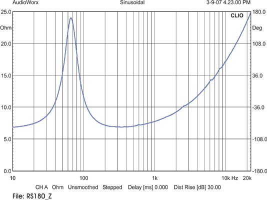
There is clearly one and only one remarkable frequency.
At higher frequencies, the impedance rises too, but there is an important difference: it caused by the inductive part of the impedance, and in order to meet the oscillation criterion the impedance needs to be purely resistive, which is not the case there.
In addition, the circuit has a 6.8nF capacitor that reduces the positive feedback above 10KHz.
Finally, this circuit is not exactly like a basic oscillator: it is equipped with an AGC.
Suppose the circuit tries to oscillate at a minor frequency: the AGC will push the gain up, and this will force oscillation at the fundamental too, and as soon as it has started, the gain will be reduced and the minor oscillation will die out naturally.
In short, there is little left to chance.
Sorry for the belated response, I missed the notification and stumble only now on the new post.
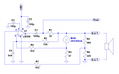
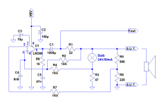
R1 and the speaker form an impedance divider, and at the resonance, its voltage is in phase with the amplifier output.
Part of this voltage is sampled by another divider formed by the bulb and R3 and sent to the + input generating positive feedback and supporting oscillations.
The - input goes to a similar divider, except it is fixed.
Under cold conditions, the bulb divider sends more signal, allowing oscillations to start, but when the filament heats up, the bridge progressively balances itself until complete equilibrium is reached.
Damn it...this is pure genious!Here is a fun application of a chipamp:
This little circuit is a sinusoidal oscillator that will adapt itself to the resonance frequency, impedance and Q of any driver presented to its test terminals.
It makes the measurement of said frequency fast, easy and accurate.
It could also find other applications: breaking-in of new speakers for example, or as a musical instrument with a variable length tube as resonator.
Have fun!
- Home
- Amplifiers
- Chip Amps
- Automatic resonance frequency finder