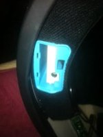
I bought this chip to install in mt bluetooth integrated motorcycle helmet because the volume is so low I can't hear anyone when they call me while wearing my helmet. It didn't come with a wiring diagram obviously bc they had no idea what I was going to use it for. Can anyone help me out?
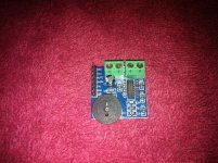
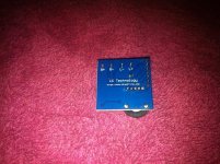
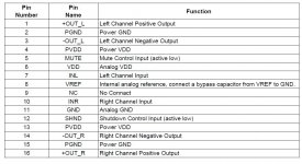
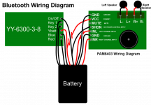
I bought this chip to install in my Bluetooth integrated motorcycle helmet because the volume is so low I can't hear anyone when they call me while wearing my helmet. It didn't come with a wiring diagram obviously bc they had no idea what I was going to use it for. Can anyone help me out? I have added some pics of exactly what I am trying to do so hopefully the visual stimulation will get someone interested in helping me out with this. Since the integrated Bluetooth chip already in the helmet is difficult to read I made an photo image replicating what the leads say on the chip that the wires are connected to. Hope this helps to help myself...lol. I also found a PDF sheet on the PAM 8403 which I uploaded also but I can't make any sense out of it. I am not an electrician but can figure it out if I just get pointed in the right direction. Thanks.
Attachments
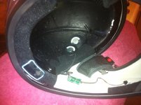
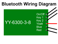
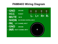
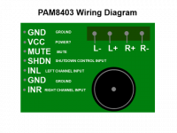
Basically my question is how do I splice the PAM8403 chip into the existing wiring configuration. I know the 4 pins L-L+R+R- go to their respective speaker but the rest I don't know what goes to what if anyone can help me out I would greatly appreciate it. Thanks.
Attachments
Wheres the question?
in R GND in L are your inputs.
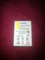
Vcc is your supply... what are you going to use? Id use 3 AA's
I dont know about those ... weird ones
Just leave them try how it sounds if it doesnt then smack those "on-off" and "mute" pins and see what happends... If this PCB had circuit it would be easy to help ..
Most of those options can be left out I belive... They might be controllable by a microprocressor that switches devices on and off, increases volume and so on.. like one of those mp3 players.
So its like a small developement kit for this amp with all its "Special effects!"
in R GND in L are your inputs.
Vcc is your supply... what are you going to use? Id use 3 AA's
I dont know about those ... weird ones
Just leave them try how it sounds if it doesnt then smack those "on-off" and "mute" pins and see what happends... If this PCB had circuit it would be easy to help ..
Most of those options can be left out I belive... They might be controllable by a microprocressor that switches devices on and off, increases volume and so on.. like one of those mp3 players.
So its like a small developement kit for this amp with all its "Special effects!"
Last edited:
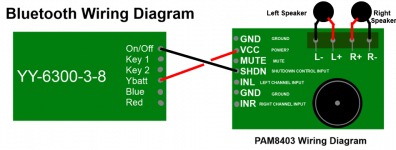
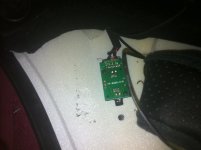
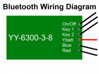
I uploaded a pic of how I wired it. I pulled everything out of the helmet so I was able to trace the wires to each speaker and splice into them. The Bluetooth turns on correctly and pairs with my iPhone but the only thing that comes out of the speakers in a little bit of crackling when I turn the Bluetooth on and off. Nothing else. What did I do wrong?
Attachments
- Status
- This old topic is closed. If you want to reopen this topic, contact a moderator using the "Report Post" button.
- Home
- Amplifiers
- Chip Amps
- PAM8403 Double Track Power Amplifier Module Volume Adjustment