Attachments
phase_accurate said:Joe R wrote:
Back then when I mentioned this LPF thingie in the other thread, my intent was different from what you are doing now.
I just want to point out the possibility of having an LPF without any buffer, which should be a piece of cake.
I don't want to claim that it sounds the same (and I don't want to try it out by now, but maybe someone else wants to do so) but the LTF would be the same if you had the 10k resistor first and the 680 Ohms resistor second with still the same capacitor from the node between them to ground.
Regards
Charles
BTW: AFAIK I was the first one mentioning the use of an LPF at the input of a GC.
Hi Charles
I hear what you're saying.
The LPF goes back to Matti Otala when he proved TIM was a factor in SS designs. Since then it became common in SS feedback designs to include a passive bandpass filter on the input. I think that is now 30 years ago or close to it. That's all history now.
Re the LPF, the one I'm using and now also by others, has a time constant near 260-270uS. If you can construct that and keep it stable, then go for it. try it and give us feedback. Or find someone who is in a position and pursuade them.
The original popular IGC (aka the one attributed to Thorsten - funny I got into trouble pointing that out earlier), has a 100K Lin pot, followed by coupling cap and 10K to the non-inverted input (-), the feedback resistor to main output pin 220K. This hasn't changed that much.
Since this is the most common configuration, how do you insert a stable (with pot changes) LPF here?
Get rid of the pot!!!!
I keep saying this, don't think, find a way of doing it and then comment.
Hands-on derived feedback, there is no substitute!
Joe R.
Hi Joe,
Are we safe to assume you advise this for a non-buffered IGC?
In which case I'd fully agree...
For a buffered input IGC I don't think it matters.
Cheers,
Get rid of the pot!!!!
Are we safe to assume you advise this for a non-buffered IGC?
In which case I'd fully agree...
For a buffered input IGC I don't think it matters.
Cheers,
phase_accurate said:I don't want to claim that it sounds the same (and I don't want to try it out by now, but maybe someone else wants to do so) but the LTF would be the same if you had the 10k resistor first and the 680 Ohms resistor second with still the same capacitor from the node between them to ground.
No Charles, it wouldn’t be the same.
Some opamps, however, can work the way you suggested, but those are exceptions. Obviously, LM1875 is not among them. Sorry, I don’t have a LM3875 spice model. Anyway, I am not an optimist. And I wouldn’t have nerves to play this game.
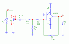
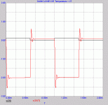
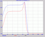
So, here we go… first, the schematic...
Attachments
Hi Pedja
This result is quite astonishing. Theoretically the two variants should behave (almost) the same way because you drive this circuit from zero impedance and it is terminated by zero impedance (virtual ground at the inverting input).
Maybe the behaviour is better with the two resistors having equal resistance (i.e. 2 x 5.1 k) and a capacitor of approx 1.8 nF.
Regards
Charles
Hello Charles,
The problem is that with capacitance going straight from the inverting input we obviously have a resonant circuit. Some resistance taller than 680 Ohms should be used to decouple this.
Yes, this will work. With 50k pot and 220k feedback, this will give LPF with -2dB at 20kHz when the pot is in central position, and -1dB at 20kHz when the pot is in minimum or maximum (assuming zero output impedance source) position.
Another (looks better) option is to use two 10k resistors, 820pF cap, 50k pot and 470k feedback resistor. This filter’s roll-off will drift between 1.3dB and 0.8dB depending on the position of the wiper.
Pedja
The problem is that with capacitance going straight from the inverting input we obviously have a resonant circuit. Some resistance taller than 680 Ohms should be used to decouple this.
phase_accurate said:Maybe the behaviour is better with the two resistors having equal resistance (i.e. 2 x 5.1 k) and a capacitor of approx 1.8 nF.
Yes, this will work. With 50k pot and 220k feedback, this will give LPF with -2dB at 20kHz when the pot is in central position, and -1dB at 20kHz when the pot is in minimum or maximum (assuming zero output impedance source) position.
Another (looks better) option is to use two 10k resistors, 820pF cap, 50k pot and 470k feedback resistor. This filter’s roll-off will drift between 1.3dB and 0.8dB depending on the position of the wiper.
Pedja
phase_accurate said:Hi Pedja
This result is quite astonishing. Theoretically the two variants should behave (almost) the same way because you drive this circuit from zero impedance and it is terminated by zero impedance (virtual ground at the inverting input).
Maybe the behaviour is better with the two resistors having equal resistance (i.e. 2 x 5.1 k) and a capacitor of approx 1.8 nF.
Regards
Charles
Not astonishing at all, this is as it should be. Looking from the feedback into the inverting input, you see 10k + 680 ohms for low frequencies > gain is about 220000/10680 about 22 times. (Ignoring the pot for the moment, ok?).
For high freqs you just see 680ohms, so the gain becomes 220000/680 = mucho higher. That gives the response peak & the square wave peaking. Nothing to do with stability, if anything the amp is more stable with the higher gain.
In fact, the peak should be much higher, but I guess the chip runs out of steam at higher frequencies.
Jan Didden
janneman said:Nothing to do with stability, if anything the amp is more stable with the higher gain.
Jan,
If I understand you, you would go that way if, say, you’ll have to have a sin(x)/x compensation for non-o/s dac (presented curve is almost perfect)? No problems with this?
In fact, the peak should be much higher, but I guess the chip runs out of steam at higher frequencies.
Probably, but more important is that you still have a low pass filter here.
Pedja
janneman said:
For high freqs you just see 680ohms, so the gain becomes 220000/680 = mucho higher. That gives the response peak & the square wave peaking. Nothing to do with stability, if anything the amp is more stable with the higher gain.
Jan Didden
Exactly.
If I may re-post the HGC or HIGC, analyse for a moment the 1n3 cap.
An externally hosted image should be here but it was not working when we last tested it.
Even if we were to unplug the tube, then 1n3 would almost certainly define stability. Gain @ 100KHz and above would still be 30dB plus.
The open loop gain drops at HF, so when we say that 10x - 20dB - of gain is required to keep the chip stable, in truth that is not the whole picture. It's too much feedback at HF that can gets the chip unstuck. Like you say: "I guess the chip runs out of steam at higher frequencies."
My guess is that it doesn't like more than 5dB of feedback above 300KHz - as I was able to trigger some misbehaviour. Feedback and slewing seems inter-related here. This is why I believe the LPF has the sonic benefits described by not a few now.
The beauty of the LPF is that in all cases it enhances stability. It also keeps the feedback loop physically ultra-short (a la Gaincard) at HF. The LPF cap and the feedback resistor to non-inverted input should have short legs.
BTW, the LPF stability works even when pots are (if you must) used.
What if there were no buffer, what if we do use a pot:
An externally hosted image should be here but it was not working when we last tested it.
The results of the pot changes:
An externally hosted image should be here but it was not working when we last tested it.
Changing two values 1) 10K Pot instead of 50K 2) the new cap value 1n7, this is the result:
An externally hosted image should be here but it was not working when we last tested it.
Better!
So IF you must have no buffer, then the better choice should be a 10K Potentiometer, and hopefully your source component won't mind. Beware of potential LF roll-off with tube preamps. But if you were using a preamp, why bother with a Pot?
Don't worry, even if no source and no Pot, our LPF cap will keep it stable. It is bomb proof!
In above cases, even in the sans tube circuits above, I keep gain at 30dB or higher under all circumstances. This goes a long way to explain why I use component values that are different from what others seem to use. I keep an eye on gain and feedback levels right across the board. I believe that this has paid of sonically!!!
Joe R.
Pedja said:
Probably, but more important is that you still have a low pass filter here.
Pedja
Good on ya, Pedja.
Keep spreading the word!!!
Joe
carlosfm said:Hi Joe,
On the schematics you posted you have 1M resistor on the feedback loop.
Isn't the gain set too high?
What about 680 ohm?

I suppose you mean 680K ohm?
Actually 1M is shown and 1M used. The gain too much? In all above circuits either tube or sans tube, the gain is around 33dB. The sans tube with 10K pot in mid value position, gain is 32dB.
THERE IS NO FEEDBACK ABOVE 200KHz !!!!
Joe R.
Joe Rasmussen said:
I suppose you mean 680K ohm?
Actually 1M is shown and 1M used. The gain too much? In all above circuits either tube or sans tube, the gain is around 33dB. The sans tube with 10K pot in mid value position, gain is 32dB.
THERE IS NO FEEDBACK ABOVE 200KHz !!!!
Joe R.
Yes, I meant 680k.
Looking at your schematic it seams to me that the gain is much higher than the 10k/220k or even 10k/330k combinations.
Correct me if I'm wrong, I may be missing something.
And 1M resitor on the feedback enters the field where you may have a little more noise than usual.
carlosfm said:
Yes, I meant 680k.
Looking at your schematic it seams to me that the gain is much higher than the 10k/220k or even 10k/330k combinations.
Correct me if I'm wrong, I may be missing something.
And 1M resitor on the feedback enters the field where you may have a little more noise than usual.
Let me assure you again, I DO use 1M.
No noise, the other 1M on the non-inverted (+) input is by-passed by 0.1 cap and the 1M feedback resistor is not dominant as the 18K + 4K7 (or 2K2 sans tube) is the dominant noise factor.
So it's more a question of whether going from 10K input value and up to 22K7 causes more noise? Not really.
So in that case the noise doesn't change significantly with 220K, 300K, 680K or 1M.
Don't worry, with 90 + dB sensititive speaker and ear millimetres from the cone... nothing!
The following THD measurement @ 8W into 8 Ohm (8V RMS):
An externally hosted image should be here but it was not working when we last tested it.
Noise floor better than 100dB. At full power this will be even better.
Now look at this:
An externally hosted image should be here but it was not working when we last tested it.
This is a tiny measly 20mW, at this point the 3875 is operating in Class A, notice the reduced distortion and lack of crossover artifacts.
Here the noise floor is about -87dB - 20mW is 400mV into 8 Ohm
Consider noise -87dB below 400mV, that's 18uV of noise.
No, be assured this is a pretty silent amp, and yes, the above examples used 1M feedback resistor!!!
Joe R.
- Status
- This old topic is closed. If you want to reopen this topic, contact a moderator using the "Report Post" button.
- Home
- Amplifiers
- Chip Amps
- Another buffer conversion


