Z-5300 Hacked
Logitech Z-5300 ... Hacked and Wireless !
I know this post is getting old and probably the original authors moved on but some people might still be interested in the alternative for the remote pod of the Z-5300 I propose!
After few hours of investigation (days in fact) I managed to get the system working without the pod but simply with an Arduino UNO and few wiring. This approach doesn’t require any soldering or even opening of the Sub unit (in fact I never opened the sub to do this hack).
From an ethical standpoint, I would not have disclosed the following information as it is Intellectual property of Logitech but considering that the product is obsolete and the spare parts are not available anymore (beside ebay market) I consider that it is people's right to build up substitute to enjoy their material longer or differently.
Furthermore, building a hacked remote control when one lost or broke it allows you to avoid a new purchase and disposal of perfectly working equipment. Thus extending the equipment lifetime is also a way to minimize out impact on environment!
I. Why hurting myself with this project
I use my Z-5300 to watch movies in 5.1 and it is also connected to an Raspberry Pi with HifiBerry and AirPlay receiver. I also still have a perfectly working remote pod so why making this project? The answer is that since I introduced a TOSLINK to RCA 5.1channel coverter, it became impossible to use the TV remote to adjust the sound volume. Thus I had to get and reach the pod to change the volume or adjust the Sub, Fad and Center levels.
This post is not covering the remote control via infrared part as there are sufficient amount of tutorials already detailing the process. Also the code is shoud be different with each remote control you may intend to use. You can still modify the code I am proposing here and make your remote controlled system for the pod substitute.
What follows is to be used at your own risk and under your own responsibility. I cannot be held responsible for any damage you may have on any equipme while trying to reproduce this system.
My electronic knowledge comes from my old student times which means around 10 years and no real practice in between so purist may find what follows a bit harsh but it worked fine for me.
I also tried to make this tutorial the simplest possible (sometime "for dummies" style) so that complete novice in electronic and Arduino can step by step reproduce the project while understanding what they are doing.
II. The remote pod: how it works
This is a pretty simply designed board composed of a selector and 3 push buttons:
Power
Mode select
Matrix
The pod also has an audio jack connector which I have never used.
Finally it is connected to the sub unit via a VGA connector similar to the one used for display.
The pod contains a microcontroller in charge of collecting the information via the buttons and send the commands accordingly to the sub internal microcontroller
III. The pod pin allocation
Based on a previous post that identified the pin (and I thank the author for that precious kick off help) I identified 3 groups for the pins:
Group Jack: this group is connected independently to the jack on the pod board. I will ignore this as it has no impact on the control electronic and is not connected to the pod micro controller.
Group power
• Pin1: GND
• Pin6: +5V
This just powers the pod electronic board of the pod. It is constantly on when you turn on the sub via the main switch in the back of the sub unit.
Group control
• Pin11: Standby
• Pin12: Mute
• Pin13: matrix
• Pin14: SCL
• Pin15: SDA
The pins 14 and 15 hold the key for the control of the unit and will have all our attention. However we will not completely ignore the pin11 and 12 as they help us turning the system out of standby mode....
IV. The control principles
a. Powering up:
The pod is always powered up by the sub when the switch is on.
b. Getting out of standby:
When you press the on/off button here is what happen in a sequence:
⁃ the standby pin 11 is set to the ground which activate the sub
⁃ The mute pin 12 is also set to the ground
⁃ The pod sends a series of bytes to the sub via the pins 14 and 15 working on i2c principles (I'll come back more in details on that later)
The series of command sent by the pod at startup has one single objective. The command series aims to gradually ramp up the volume in order to reach the last level set by the user when the latter turned the pod off. This user setting is stored in the pod and not in sub. For proof if you set the volume to a certain level, turn off the pod, disconnect the pod while maintaining the main general switch on, the unit will get in standby mode. Reconnecting the pod and turning it back on will not set the volume to last user setting but to minimum. Note that I say “minimum” and not zero. The zero for the pod means “volume to the maximum”. I'll come back on that.
c. Matrix button
I never liked the effect of this button but anyway. Pressing the button will set pin 13 to ground activating the effect. The pod also sends a tiny volume reduction command in parallel more for user comfort than for actual usefulness.
d.mode selector
The mode selector has no direct impact on the sub. It simply indicate to the pod what type of command to send to the sub when turning the selector. It also starts a timer to get back to volume mode if the user does not change the setting of the selected parameter after a certain time.
d.the selector
The selector is what triggers the command. It sends 2 types of indications to the pod's Micro controller: up or down
Every time you turn it and increase or decrease by one indentation the micro controller sends to the sub one command and one only!
V. The commands
The pod communicates with the sub using the i2c/twi standard on pin 14 & 15. Please go on wiki if you don't see what I am talking about.
Basically each command is composed of 3 instructions:
⁃ the address: the pod is the master and is sending the address 68 which is the sub microcontroller address. This is also followed by the write instruction to indicate to the sub that more will follow
⁃ The speaker code give an indication as of which speaker the command will apply. If for example this code is 0 that means general volume. I'll detail the different code I identified later
⁃ The level to be set to.
As an example if I want to set the volume to the middle position, here is what happens in a sequence
1. Start
2. Address 68 + 0 write
3. Nature 0
4. Level 30
5. Stop
In human world that would mean:
1. "Hello everyone I am on the line as the master in the pod and I am opening the channel!"
2. "Hey sub! Yes, you with the number 68. I am about to give you instructions"
3. "So you will now change the volume"
4. "You will set it to 30 on a scale from 0 to 61"
5. "That's it for now I hang up!"
In the i2c standard, with exception to the start and stop signals each step corresponds to one byte (8bits) separated by an acknowledgment 0 bit emitted by the sub. That's theory because as you will see reality is a bit more complex. Indeed our beloved sub is acknowledging by sending a 1 bit in spite of the standard definition.
Having said that here are the different commands I could identify:
Address: 68 (7bit) + 0 write bit
Which in bit world correspond to 10001000
Speaker codes:
• 0 (00000000 in bit world) applies to all speaker simultaneously and thus aims to set the volume
• 1: Front left speaker. The standard remote pod does not use it. If you want to finer tune the setup with the remote you may be interested.
• 2: Front right speaker. Idem as FL.
• 3: Center speaker
• 4: Rear Left speaker (RL)
• 5: Rear Right speaker (RR)
• 7: Subwoofer (SW)
• 8: this code is not designing any speaker (obviously) but is used to mute or unmute one or several specific speakers in the system
Level:
For volume:
• 80: equivalent to mute
• 61: level minimum
• 0: level maximum
• All values between 61 and 0 indicates a level
For Subwoofer
• 85: full left
• 80 almost full right
• 89 full right
• All value between 85 and 80 indicates the centering position
For center
• 12: sub to minimum
• 0. Sub to maximum
• All values between 12 and 0 indicate the sub level to adopt
For fader: (applies to RR &RL)
• 12: full back
• 0: full front
• All values in between
The same code range applies also for the front speakers but the pod is not equipped to send any signal applicable to front right and left speakers. The system is set at maximum 0 as initial setup.
The speaker code 8 works differently compared to the previous ones.
As explained the code 8 aims to Mute or Unmute the volume of one or several speaker depending on the values. With the pod the commands using the speaker code 8 is sent when the Center or Fader volumes are turned to minimum. To understand how the command works requires decomposing the Byte that is sent as associated instruction for speaker code 8.
When the Fader is set to minimum, the pod sends the instruction [8 ; 6] and thus turns both Rear speakers back on.
In binary 6 is equivalent to:
[ 0 | 0 | 0 | 0| 0 | 1 | 1 | 0 ]
When turning the fader back up, the first command will be [8;0] to turn the Rear speakers back on.
If you measure the same thing on the Center functions, the pod will switch the center speaker on mute by sending the instruction [8 ; 8].
[ 0 | 0 | 0 | 0| 1 | 0 | 0 | 0 ]
In fact exact bit set to 1 in the instruction byte will set the corresponding speaker on mute.
We can match each speaker with the following mapping:
[ 0 | 0 | FL | FR| C | RL | RR | 0 ]
As an example, If I want to mute all the speaker on the rights and the center, I should submit the command: [ 8 , 26]
Which in binary mapping would give : [ 0 | 0 | 0 | 1| 1 | 0 | 1 | 0 ]
Before setting a volume value for a specific speaker, don’t forget to set it back on unmute by changing the bit associated down to 0 in the command.
Now that we understand the working principles better, let's start creating our own pod
VI. The electronic setup
What follows is pure prototyping. It works (for me at least) but is far from representing a finalized solution. I hope it will get you through the difficulties I encountered to be able to control the sub with an alternative hardware to the supplied pod (especially if you lost it).
The design I propose here doesn’t include either a remote control capability. If you wish to get more details on how to set a IR and basics for remote control please visit the following website: Arduino Infrared Remote tutorial - All
a. Material
⁃ An Arduino UNO
⁃ A breadboard
⁃ A VGA separator ( I personal used a VGA extender cable I sacrificed to do the separation of the pin cables)
⁃ A VGA cable with a female connector (usually in extenders)
⁃ Some male female inverters (depends on the cable and separator configuration you have)
⁃ 4 push buttons
⁃ 3 resistors 470 Ohms
⁃ 4 resistors 220 Ohms
⁃ 1 resistors 1 kOhms
⁃ 4 resistors 10 kOhms
⁃ 2 resistors 30 Ohms
⁃ 1 capacitor 1microF
⁃ 4 LED (same or different colors as your preference)
⁃ Jumper cables
b. Build up the electronic circuit
We are going to make a simple 4 buttons pod:
• On/Off
• Selector
• Volume UP
• Volume DOWN
Set up the 3 buttons the same way with one resistance to the ground and the 5v connected to the push button
The line between the resistance and the button shall be connected to one digital output from the Arduino
Using the VGA separator, connect the following pins to the Arduino:
Pin 1 ground to Arduino ground
Pin 6 5v to Arduino 5v ( optional if Arduino is powered via USB)
Pin14 to SCL of the Arduino
Pin15 to SDA of the Arduino
If you want to focus on the volume control first and see the on/off function for another time then directly connect the pins 11 and 12 to the ground. Otherwise connect them to some Arduino digital output with a 470 Ohm resistance to protect.
That's it you have created the remote! At least from a hardware perspective.
It should look like something like this: (pin connection on the picture may differ from the picture)
VII. Programing the Arduino
Some of you may tell me that they tried this but never get the Arduino or any i2c master device successfully sending commands to the sub.
Some people have successfully managed to send i2c commands by directly soldering the SCL and SDA from the Arduino to the sub internal microcontroller because the i2c commands were not accepted via the VGA. I have managed to have it working without that method because I found out that the system is not complying with all specification of the i2c standard!
When you look at the i2c specs from NXP and the way the Arduino Wire library works, after each byte transmitted the slave has to Acknowledge reception via a 0bit!
That's not the case with the sub microcontroller in the Z5300. It acknowledges by sending a 1bit which leads the Arduino to think that the sub did not acknowledge reception.
As a consequence the Arduino immediately stops sending information after the address byte.
The sub thinks then that the pod only sends a series of zero which means "volume to max" and then set all the speakers to maximum.
This is the real challenge I had to face here!
As the only thing you have control on is the Arduino software, my idea was to adapt the Wire library so that the Acknowledgement becomes a 1bit instead of a 0 to adapt the the protocol to the one expected by the Subwoofer.
I went and reviewed the Wire.h file and found out that the real file to modify should be one of the files in the library folders called twi.h.
You will find the right file at the following folder (I’m using a Mac, I have no idea where the file might be on windows… sorry) in the Arduino application packages:
Contents/Java/hardware/tools/avr/avr/include/util/twi.h
The simple thing to do (after saving a copy of the original twi.h file just in case) is to invert the NACK and ACK value definition for the master transmitters MT.
In the twi.h file, modify the following values to reverse the Acknowledgment protocol:
Once done, you just have to write the following code lines and load the program in the Arduino. If you are not satisfied with the pin allocation for the button and the LED, you just have to change the values in the allocation code line in the beginning of the following program in the Arduino programmer software:
Congratulation, you should now have a running program.
You can now adapt the remote to your needs with more buttons or like me add an infrared receptor to have it remote controlled (which that code already enables.
The previous code is not able to turn individually the speaker on mute. I haven’t done the program with code 8 functions yet (mentioned earlier).
In the meantime this solution is a pretty robust approach to make a substitute to the original control pod in case you lost or broke it (and don’t want to pay $60, or € on a used spare)
Enjoy!!!
Logitech Z-5300 ... Hacked and Wireless !
I know this post is getting old and probably the original authors moved on but some people might still be interested in the alternative for the remote pod of the Z-5300 I propose!
After few hours of investigation (days in fact) I managed to get the system working without the pod but simply with an Arduino UNO and few wiring. This approach doesn’t require any soldering or even opening of the Sub unit (in fact I never opened the sub to do this hack).
From an ethical standpoint, I would not have disclosed the following information as it is Intellectual property of Logitech but considering that the product is obsolete and the spare parts are not available anymore (beside ebay market) I consider that it is people's right to build up substitute to enjoy their material longer or differently.
Furthermore, building a hacked remote control when one lost or broke it allows you to avoid a new purchase and disposal of perfectly working equipment. Thus extending the equipment lifetime is also a way to minimize out impact on environment!
I. Why hurting myself with this project
I use my Z-5300 to watch movies in 5.1 and it is also connected to an Raspberry Pi with HifiBerry and AirPlay receiver. I also still have a perfectly working remote pod so why making this project? The answer is that since I introduced a TOSLINK to RCA 5.1channel coverter, it became impossible to use the TV remote to adjust the sound volume. Thus I had to get and reach the pod to change the volume or adjust the Sub, Fad and Center levels.
This post is not covering the remote control via infrared part as there are sufficient amount of tutorials already detailing the process. Also the code is shoud be different with each remote control you may intend to use. You can still modify the code I am proposing here and make your remote controlled system for the pod substitute.
What follows is to be used at your own risk and under your own responsibility. I cannot be held responsible for any damage you may have on any equipme while trying to reproduce this system.
My electronic knowledge comes from my old student times which means around 10 years and no real practice in between so purist may find what follows a bit harsh but it worked fine for me.
I also tried to make this tutorial the simplest possible (sometime "for dummies" style) so that complete novice in electronic and Arduino can step by step reproduce the project while understanding what they are doing.
II. The remote pod: how it works
This is a pretty simply designed board composed of a selector and 3 push buttons:
Power
Mode select
Matrix
The pod also has an audio jack connector which I have never used.
Finally it is connected to the sub unit via a VGA connector similar to the one used for display.
The pod contains a microcontroller in charge of collecting the information via the buttons and send the commands accordingly to the sub internal microcontroller
III. The pod pin allocation
Based on a previous post that identified the pin (and I thank the author for that precious kick off help) I identified 3 groups for the pins:
Group Jack: this group is connected independently to the jack on the pod board. I will ignore this as it has no impact on the control electronic and is not connected to the pod micro controller.
Group power
• Pin1: GND
• Pin6: +5V
This just powers the pod electronic board of the pod. It is constantly on when you turn on the sub via the main switch in the back of the sub unit.
Group control
• Pin11: Standby
• Pin12: Mute
• Pin13: matrix
• Pin14: SCL
• Pin15: SDA
The pins 14 and 15 hold the key for the control of the unit and will have all our attention. However we will not completely ignore the pin11 and 12 as they help us turning the system out of standby mode....
IV. The control principles
a. Powering up:
The pod is always powered up by the sub when the switch is on.
b. Getting out of standby:
When you press the on/off button here is what happen in a sequence:
⁃ the standby pin 11 is set to the ground which activate the sub
⁃ The mute pin 12 is also set to the ground
⁃ The pod sends a series of bytes to the sub via the pins 14 and 15 working on i2c principles (I'll come back more in details on that later)
The series of command sent by the pod at startup has one single objective. The command series aims to gradually ramp up the volume in order to reach the last level set by the user when the latter turned the pod off. This user setting is stored in the pod and not in sub. For proof if you set the volume to a certain level, turn off the pod, disconnect the pod while maintaining the main general switch on, the unit will get in standby mode. Reconnecting the pod and turning it back on will not set the volume to last user setting but to minimum. Note that I say “minimum” and not zero. The zero for the pod means “volume to the maximum”. I'll come back on that.
c. Matrix button
I never liked the effect of this button but anyway. Pressing the button will set pin 13 to ground activating the effect. The pod also sends a tiny volume reduction command in parallel more for user comfort than for actual usefulness.
d.mode selector
The mode selector has no direct impact on the sub. It simply indicate to the pod what type of command to send to the sub when turning the selector. It also starts a timer to get back to volume mode if the user does not change the setting of the selected parameter after a certain time.
d.the selector
The selector is what triggers the command. It sends 2 types of indications to the pod's Micro controller: up or down
Every time you turn it and increase or decrease by one indentation the micro controller sends to the sub one command and one only!
V. The commands
The pod communicates with the sub using the i2c/twi standard on pin 14 & 15. Please go on wiki if you don't see what I am talking about.
Basically each command is composed of 3 instructions:
⁃ the address: the pod is the master and is sending the address 68 which is the sub microcontroller address. This is also followed by the write instruction to indicate to the sub that more will follow
⁃ The speaker code give an indication as of which speaker the command will apply. If for example this code is 0 that means general volume. I'll detail the different code I identified later
⁃ The level to be set to.
As an example if I want to set the volume to the middle position, here is what happens in a sequence
1. Start
2. Address 68 + 0 write
3. Nature 0
4. Level 30
5. Stop
In human world that would mean:
1. "Hello everyone I am on the line as the master in the pod and I am opening the channel!"
2. "Hey sub! Yes, you with the number 68. I am about to give you instructions"
3. "So you will now change the volume"
4. "You will set it to 30 on a scale from 0 to 61"
5. "That's it for now I hang up!"
In the i2c standard, with exception to the start and stop signals each step corresponds to one byte (8bits) separated by an acknowledgment 0 bit emitted by the sub. That's theory because as you will see reality is a bit more complex. Indeed our beloved sub is acknowledging by sending a 1 bit in spite of the standard definition.
Having said that here are the different commands I could identify:
Address: 68 (7bit) + 0 write bit
Which in bit world correspond to 10001000
Speaker codes:
• 0 (00000000 in bit world) applies to all speaker simultaneously and thus aims to set the volume
• 1: Front left speaker. The standard remote pod does not use it. If you want to finer tune the setup with the remote you may be interested.
• 2: Front right speaker. Idem as FL.
• 3: Center speaker
• 4: Rear Left speaker (RL)
• 5: Rear Right speaker (RR)
• 7: Subwoofer (SW)
• 8: this code is not designing any speaker (obviously) but is used to mute or unmute one or several specific speakers in the system
Level:
For volume:
• 80: equivalent to mute
• 61: level minimum
• 0: level maximum
• All values between 61 and 0 indicates a level
For Subwoofer
• 85: full left
• 80 almost full right
• 89 full right
• All value between 85 and 80 indicates the centering position
For center
• 12: sub to minimum
• 0. Sub to maximum
• All values between 12 and 0 indicate the sub level to adopt
For fader: (applies to RR &RL)
• 12: full back
• 0: full front
• All values in between
The same code range applies also for the front speakers but the pod is not equipped to send any signal applicable to front right and left speakers. The system is set at maximum 0 as initial setup.
The speaker code 8 works differently compared to the previous ones.
As explained the code 8 aims to Mute or Unmute the volume of one or several speaker depending on the values. With the pod the commands using the speaker code 8 is sent when the Center or Fader volumes are turned to minimum. To understand how the command works requires decomposing the Byte that is sent as associated instruction for speaker code 8.
When the Fader is set to minimum, the pod sends the instruction [8 ; 6] and thus turns both Rear speakers back on.
In binary 6 is equivalent to:
[ 0 | 0 | 0 | 0| 0 | 1 | 1 | 0 ]
When turning the fader back up, the first command will be [8;0] to turn the Rear speakers back on.
If you measure the same thing on the Center functions, the pod will switch the center speaker on mute by sending the instruction [8 ; 8].
[ 0 | 0 | 0 | 0| 1 | 0 | 0 | 0 ]
In fact exact bit set to 1 in the instruction byte will set the corresponding speaker on mute.
We can match each speaker with the following mapping:
[ 0 | 0 | FL | FR| C | RL | RR | 0 ]
As an example, If I want to mute all the speaker on the rights and the center, I should submit the command: [ 8 , 26]
Which in binary mapping would give : [ 0 | 0 | 0 | 1| 1 | 0 | 1 | 0 ]
Before setting a volume value for a specific speaker, don’t forget to set it back on unmute by changing the bit associated down to 0 in the command.
Now that we understand the working principles better, let's start creating our own pod
VI. The electronic setup
What follows is pure prototyping. It works (for me at least) but is far from representing a finalized solution. I hope it will get you through the difficulties I encountered to be able to control the sub with an alternative hardware to the supplied pod (especially if you lost it).
The design I propose here doesn’t include either a remote control capability. If you wish to get more details on how to set a IR and basics for remote control please visit the following website: Arduino Infrared Remote tutorial - All
a. Material
⁃ An Arduino UNO
⁃ A breadboard
⁃ A VGA separator ( I personal used a VGA extender cable I sacrificed to do the separation of the pin cables)
⁃ A VGA cable with a female connector (usually in extenders)
⁃ Some male female inverters (depends on the cable and separator configuration you have)
⁃ 4 push buttons
⁃ 3 resistors 470 Ohms
⁃ 4 resistors 220 Ohms
⁃ 1 resistors 1 kOhms
⁃ 4 resistors 10 kOhms
⁃ 2 resistors 30 Ohms
⁃ 1 capacitor 1microF
⁃ 4 LED (same or different colors as your preference)
⁃ Jumper cables
b. Build up the electronic circuit
We are going to make a simple 4 buttons pod:
• On/Off
• Selector
• Volume UP
• Volume DOWN
Set up the 3 buttons the same way with one resistance to the ground and the 5v connected to the push button
The line between the resistance and the button shall be connected to one digital output from the Arduino
Using the VGA separator, connect the following pins to the Arduino:
Pin 1 ground to Arduino ground
Pin 6 5v to Arduino 5v ( optional if Arduino is powered via USB)
Pin14 to SCL of the Arduino
Pin15 to SDA of the Arduino
If you want to focus on the volume control first and see the on/off function for another time then directly connect the pins 11 and 12 to the ground. Otherwise connect them to some Arduino digital output with a 470 Ohm resistance to protect.
That's it you have created the remote! At least from a hardware perspective.
It should look like something like this: (pin connection on the picture may differ from the picture)
VII. Programing the Arduino
Some of you may tell me that they tried this but never get the Arduino or any i2c master device successfully sending commands to the sub.
Some people have successfully managed to send i2c commands by directly soldering the SCL and SDA from the Arduino to the sub internal microcontroller because the i2c commands were not accepted via the VGA. I have managed to have it working without that method because I found out that the system is not complying with all specification of the i2c standard!
When you look at the i2c specs from NXP and the way the Arduino Wire library works, after each byte transmitted the slave has to Acknowledge reception via a 0bit!
That's not the case with the sub microcontroller in the Z5300. It acknowledges by sending a 1bit which leads the Arduino to think that the sub did not acknowledge reception.
As a consequence the Arduino immediately stops sending information after the address byte.
The sub thinks then that the pod only sends a series of zero which means "volume to max" and then set all the speakers to maximum.
This is the real challenge I had to face here!
As the only thing you have control on is the Arduino software, my idea was to adapt the Wire library so that the Acknowledgement becomes a 1bit instead of a 0 to adapt the the protocol to the one expected by the Subwoofer.
I went and reviewed the Wire.h file and found out that the real file to modify should be one of the files in the library folders called twi.h.
You will find the right file at the following folder (I’m using a Mac, I have no idea where the file might be on windows… sorry) in the Arduino application packages:
Contents/Java/hardware/tools/avr/avr/include/util/twi.h
The simple thing to do (after saving a copy of the original twi.h file just in case) is to invert the NACK and ACK value definition for the master transmitters MT.
In the twi.h file, modify the following values to reverse the Acknowledgment protocol:
/* Master Transmitter */
/** \ingroup util_twi
\def TW_MT_SLA_ACK
SLA+W transmitted, ACK received */
#define TW_MT_SLA_ACK 0x20 // Original value 0x18
/** \ingroup util_twi
\def TW_MT_SLA_NACK
SLA+W transmitted, NACK received */
#define TW_MT_SLA_NACK 0x18 // Original value 0x20
/** \ingroup util_twi
\def TW_MT_DATA_ACK
data transmitted, ACK received */
#define TW_MT_DATA_ACK 0x30 //Original value 0x28
/** \ingroup util_twi
\def TW_MT_DATA_NACK
data transmitted, NACK received */
#define TW_MT_DATA_NACK 0x28 // Original value 0x30
Once done, you just have to write the following code lines and load the program in the Arduino. If you are not satisfied with the pin allocation for the button and the LED, you just have to change the values in the allocation code line in the beginning of the following program in the Arduino programmer software:
#include <Wire.h> //Library Wire with modified Acknowledged function in I2C protocol
#include <IRremote.h> // Optional Remote control library (for those who want to control the Z5300 with a remote control
//Bouton
const char up_pin = 2;// Up
const char dow_pin = 3;// Down
const int onoff_pin = 4; //on/off
const char sel_pin = 5; // Option Selector
//OUtput fonctions to SUB
const char stdy_pin = 10; //standby
const char mute_pin = 11; // Mute
const char mat_pin = 12;// Matrix
//LED status indicator
const char red_pin = 6; //Red LED for Volume
const char gre_pin = 7; // Green LED for Sub
const char yel_pin = 8; //Yellow PIN for Fader
const char blu_pin = 9; // Blue LED for Center
//Pin for Remote Control Input
const char irr_pin = 13; //IRRemote input (if any IR detector) on pin 13
int select = 0;// 0 volume, 4
int vol = 80;//original 80 for test 30
int sub = 82;// Original volume for the sub set to 82 initial setup when sub turned on
int fad = 6; / Original volume for the fader set to 6 initial setup when sub turned on
int cent = 6;/ Original volume for the Center set to 6 initial setup when sub turned on
int lr = 0;// Original volume for the sub set to 82 initial setup when sub turned on
int timer_select;
bool onoff= 0;//On off indicator boolean
bool mute = 0;//Mute indicator boolean
bool matrix = 0;// Matrix mode indicator boolean (not used here. Just add a button on a pin and an associated function to toogle mat_pin with digitalWrite function)
IRrecv irrecv(irr_pin);//Start IR Remote receiver
decode_results results;// store the result of the last IR command received
void setup() {
//Setup of Serial IN/OUPUTS
Serial.begin(9600);
Wire.begin(); // join i2c bus (address optional for master)
irrecv.enableIRIn(); // Start the IR Remote receiver
// Buttons OUTPUT
pinMode(up_pin, INPUT);//up Button
pinMode(dow_pin, INPUT);//down Button
pinMode(onoff_pin, INPUT);//on/off button
pinMode(sel_pin, INPUT);//selector pin
//output onoff mute and matrix for the SUB
pinMode(stdy_pin,OUTPUT);
pinMode(mute_pin,OUTPUT);
pinMode(mat_pin,OUTPUT);
//Setup off mode and matrix OFF
digitalWrite(stdy_pin,HIGH);
digitalWrite(mute_pin,HIGH);
digitalWrite(mat_pin,LOW);
// LED setting
pinMode(red_pin,OUTPUT);//set red LED for volume
pinMode(gre_pin,OUTPUT);//set green LED for sub
pinMode(yel_pin,OUTPUT);//set yellow LED for Fader
pinMode(blu_pin,OUTPUT);//set blue LED for Center
// Set the off status as startup status
digitalWrite(stdy_pin,HIGH);
digitalWrite(mute_pin,HIGH);
digitalWrite(mat_pin,HIGH);
Subset(0,80);//Reinitialisation of sound to lowest
Serial.println("Good to control!");
}
void loop() {
int temp_timer = millis();//record time for the loop cycle
// ON/OFF Toogle Button
if(digitalRead(onoff_pin)==HIGH){
Toogleonoff();
delay(100);
}
if(onoff==1){// give access to functions volume capable of adjusting the vol varialble only if the system is on
// Mode Selection Button
if(digitalRead(sel_pin)==HIGH){
select=modeselect(select);
timer_select=millis();
// matrix=abs(matrix-1);
//digitalWrite(mat_pin,matrix);
//delay(100);
while(digitalRead(sel_pin)==HIGH){
}
}
// BUTTON VOLUME UP
if(digitalRead(up_pin)==HIGH){
digitalWrite(red_pin,LOW);// turnoff Red LED to show command reception
timer_select=millis();// reset the automatic return to volume mode to new value due to press button action
switch(select){//select the mode and command to send accordingly
case 0:
vol=volumecal(vol,1);
Subset(select,vol);//decrementation the volume level
break;
case 7:
sub=Calc_Sub(sub,1); // decementation of Sub level
Subset(select,sub); //Set level to Subwoofer
break;
case 4:
fad=Calc_FadCent(fad,1);// decementation of Fader level
Subset(select,fad); //Set level to Rear Left Speaker
Subset(select+1,fad); //Set level to Rear Rigth Speaker
break;
case 3:
cent=Calc_FadCent(cent,1);// decementation of SubCenter level
Subset(select,cent); //Set level to Center Speaker
break;
case 1:
lr=Calc_FadCent(lr,1); // decementation of Front level
Subset(1,lr); //Set level to Front Left Speaker
Subset(2,lr); //Set level to Front Right Speaker
break;
}
delay(100);
digitalWrite(red_pin,HIGH); // turn LED Red back ON
}
// BUTTON VOLUME DOWN Activate
if(digitalRead(dow_pin)==HIGH){
timer_select=millis();
switch(select){
case 0:
vol=volumecal(vol,0);
Subset(select,vol);//decrementation the volume level
break;
case 7:
sub=Calc_Sub(sub,0);
Subset(select,sub);//Volume Subwoofer
break;
case 4:
fad=Calc_FadCent(fad,0);
Subset(select,fad);//Volume Rear Left
Subset(select+1,fad);//Volume Rear Right
break;
case 3:
cent=Calc_FadCent(cent,0);
Subset(select,cent);
break;
case 1:
lr=Calc_FadCent(lr,0);
Subset(1,lr);//Volume Front Left
Subset(2,lr);//Volume Front Right
break;
}
delay(100);
}
}
if(temp_timer-timer_select>5000 & select!=0){ // return to volume mode if no button is pressed after 5 seconds
select=modeselect(2);// set on general volume mode
}
/*Remote control Parts
* This section until the end of the loop function enables to control the Mute and the general volume via the remote control
* This is using an infrared detector suitable with the remote control you wish to use
* This code is adapted to my LG TV remote control and will not work if you have a different brand or model
* If you wish to use the following you will have to adapt the code to the remote you wish to use therefore you should identify the way
* you can control the remote you wish to use with the Arduhno and understand its protocol (see IRRemote tutorial to proceed)
*/
if (irrecv.decode(&results)) {
Serial.println(results.value, HEX);
if(results.value==0x20DF4EB1){ // code received for ON/OFF of the Unit
Toogleonoff();
delay(100);
}
if(onoff==1){
if( results.value==0x20DF906F){
mute=abs(mute-1);
//digitalWrite(mute_pin,mute);
digitalWrite(red_pin,LOW);
if(mute==1){
digitalWrite(mute_pin,HIGH);
//Subset(8,32);
}
else{
digitalWrite(mute_pin,LOW);
// Subset(8,31);
}
delay(100);
digitalWrite(red_pin,HIGH);
}
if(results.value==0x20DF40BF){
bailout:
digitalWrite(red_pin,LOW);// create a blink LED to acknowledge remote data reception
vol=volumecal(vol,1); //decrementation of vol value to increase the volume level
Subset(0,vol); // apply the volume instruction ot the SUB
irrecv.resume();
int tim1=millis();
int tim2;
while(irrecv.decode(&results)==0 && (tim2-tim1)<200 ){
tim2=millis();
delay(50);
digitalWrite(red_pin,HIGH);
}
if (irrecv.decode(&results)){
goto bailout;
}
//irrecv.resume();
delay(100);
digitalWrite(red_pin,HIGH);
}
else if(results.value==0x20DFC03F){
keepdown:
digitalWrite(red_pin,LOW);// create a blink LED to acknowledge remote data reception
vol=volumecal(vol,0); //decrementation the volume level
Subset(0,vol); // apply the volume instruction ot the SUB
irrecv.resume();
int tim1=millis();
int tim2;
while(irrecv.decode(&results)==0 && (tim2-tim1)<200 ){
tim2=millis();
delay(50);
digitalWrite(red_pin,HIGH);
}
if (irrecv.decode(&results)){
goto keepdown;
}
delay(100);
digitalWrite(red_pin,HIGH);
}
}
irrecv.resume();
/*************************************************/
}
}
/* Function volumecal
* Desc Increase or decrease the input value to be used for the volume incrementation applied.
* Function considers the sides effects and
* Input x: integer current volume level value
* sens: boolean intdicating the increase (1) or the decrease (0) of volume level value byt one unit
* Output Return a value for the
*/
int volumecal(int x, bool sens){
if (x==80){
return 80-19*sens;
}
else if(x==61){
return 60+abs(sens-1)*20;
}
else{
return max(x-1+abs(sens-1)*2,0);
}
}
/* Function volumeset(int )
* Desc send the command to the sub
*
* Input nat: nature or parameter to be sent
* x: level of information to be sent
*/
void Subset(int nat,int x){
Wire.beginTransmission(68); // transmit to device #68
Wire.write(nat);
Wire.write(x);
Wire.endTransmission();
Serial.print(nat);
Serial.print(", ");
Serial.println(x);
}
/* Function Toogleonoff()
* Desc Toogle On/Off of the sub with a smooth ramp up or down effect on the volume
*
* Input
*/
void Toogleonoff(){
select = modeselect(2);
onoff=abs(onoff-1);//Toogle the value onoff as boolean
//Serial.println("ON/OFF");
int x=(vol)*onoff+80*abs(onoff-1);// target Volume to reach in the process
int temp=80*onoff+(vol)*abs(onoff-1); //original standpoint from where to start in the process
//turn the SUB ON in case the sub is currently off
if(onoff==1){
digitalWrite(stdy_pin,LOW);
delay(50);
digitalWrite(mute_pin,LOW);
delay(50);
}
//Ramp-up or down the sound depending the toogle to get from or to the set volume level
while(x!=temp){
Subset(0,temp);
delay(50);
temp=volumecal(temp,onoff);
}
//Turn the SUB OFF in case the sub is currently on
if(onoff==0){
Subset(0,80);
digitalWrite(mute_pin,HIGH);
delay(50);
digitalWrite(stdy_pin,HIGH);
delay(50);
}
delay(10);
digitalWrite(red_pin,onoff);
}
/* Function Calc_FadCent
* Desc Toogle On/Off of the sub with a smooth ramp up or down effect on the volume
*
* Input
*/
int Calc_FadCent(int x, bool sens){
return min(12,max(x-1+abs(sens-1)*2,0));
}
int Calc_Sub(int x, bool sens){
if(x==89){
return max(89*sens,80+sens*9);
}
if(x==80){
return 81+sens*8;
}
else{
return min(85,max(x-1+abs(sens-1)*2,80));
}
}
int modeselect(int x){
//Reset all LED to off mode
digitalWrite(red_pin,LOW);// volume
digitalWrite(gre_pin,LOW);// Subwoofer
digitalWrite(yel_pin,LOW);//Fader
digitalWrite(blu_pin,LOW);//Center
switch(x){
case 0:
digitalWrite(gre_pin,HIGH);
return 7;
break;
case 7:
digitalWrite(yel_pin,HIGH);
return 4;
break;
case 4:
digitalWrite(blu_pin,HIGH);
return 3;
break;
case 3:
// Optional Front Left,
return 1;
break;
default:
digitalWrite(red_pin,HIGH);
return 0;
break;
}
}
Congratulation, you should now have a running program.
You can now adapt the remote to your needs with more buttons or like me add an infrared receptor to have it remote controlled (which that code already enables.
The previous code is not able to turn individually the speaker on mute. I haven’t done the program with code 8 functions yet (mentioned earlier).
In the meantime this solution is a pretty robust approach to make a substitute to the original control pod in case you lost or broke it (and don’t want to pay $60, or € on a used spare)
Enjoy!!!
Attachments

Hey,
This post is old and many people may have moved on the Z5300 Pod case but some other lacking the remote pod might be interested in the solution I managed to come up with.
The previous issues on the I2C connection to the Sub was due to the fact that the Sub doesn't follow the I2C protocol according to the standard. Instead it is reversing the Acknowledgement bit between the message transmitted.
I posted a PDF with the solution to build a new prototype pod with an Arduino. i also used a Infrared sensor to enable remote control with a TV remote. This of course requires you to adapt the code according to your model of remote.
I am currently building a more finished and smaller version based on the Arduino nano v3.0. I'll keep you posted!
Attachments
Hi, sorry for bringing up this thread again. I've got a z-5300 and it was working perfectly until a few days ago, long history short... the transformer went away. I'd like to repair it, but I haven't found a way to open the subwoofer and I don't want to break it just to see the transformer values, I can't test the output voltages because it's shorted.
Would you be so kind to tell me the voltages of the green-black-blue wires? That way I'd be able to find a replacement and attach it on the back of the amp.
Thank you very much in advance.
Hey,
This post is old and many people may have moved on the Z5300 Pod case but some other lacking the remote pod might be interested in the solution I managed to come up with.
The previous issues on the I2C connection to the Sub was due to the fact that the Sub doesn't follow the I2C protocol according to the standard. Instead it is reversing the Acknowledgement bit between the message transmitted.
I posted a PDF with the solution to build a new prototype pod with an Arduino. i also used a Infrared sensor to enable remote control with a TV remote. This of course requires you to adapt the code according to your model of remote.
I am currently building a more finished and smaller version based on the Arduino nano v3.0. I'll keep you updated!
Attachments
The remote is based on the I2C protocol that has a maximum distance of about 1-2m on its own. If you wanted to do a wired-based solution as you are proposing. You would have to add in an I2C Extender IC http://www.ti.com/lit/ds/symlink/p82b715.pdf on pins 14/15 and then add twisted pair cable between them (Ethernet Cable Cat5e,etc). I've tested these IC's out for other projects and they work well. The rest of the wires you could just make straight through on the Ethernet Cable solder the VGA connectors on how you see fit with the right pinout.
Hi! New user here with the same system as you have described here.
I, oddly have found a few things myself. But first a little background:
I acquired the z5300e system quite a while ago from a friend as a gift and I've recently started to "finish" my garage. As part of this job, I thought it'd be neat to wire the garage for surround sound, so using the 5300, I set to it.
Using RCA extensions, VGA extenders, wall plates, and a lot of sweat and time cramped in the attic, I finally finished wiring the entire system to place each speaker in its respective corner/center while creating a shelf for the subwoofer above the garage door. I intended to place the control pod near the entry to the house so I could power on the system when I enter the garage, and turn it off when I go back inside.
After doing all of this, and failing to power the control pod at the extended distance I started doing some research and found (like many have already) that VGA extenders cannot be used to extend the pot further from the subwoofer enclosure. That's damn annoying, but I figured I'd still attempt further.
In a funny set of circumstances (and ordering the wrong cabling) I picked up a gender changer I needed to connect the system. Here's a simple schematic of what I have going on:
Logitech z5300e-->F/F Gender changer--->M/M 1.5' VGA extension cable--->wall plate(F/F VGA coupler)--->50' M/M VGA cable--->wall plate(F/F VGA coupler)---->M/M Gender changer---->Control pod
So first off, yes I realize I have quite a few unnecessary joints in there (specifically the gender changers) but I wasn't very attentive when ordering the parts.....
Next, I thought I'd share some findings. In realizing my error, I had to make several (separate) purchases of equipment to complete my design. So, initially, to test everything (without the extension leg) I affixed the control pod to the sub enclosure above the garage door and cranked the volume to maximum. With my iPhone connected to the stereo jack (green) I adjusted the sub output until it fit my liking.
Once I received all of the necessary gender changers, I wired the system according to my design (above) and found that the system worked as I had designed with one exception. I had zero control with the pod. No lights, no power, nothing. This isn't the worst possible thing that happened actually because with the volume maxed out initially, I could control all of the sound with my iPod, albeit the control was linear. I didn't have subwoofer control, fade, or center control. Annoyed, I figured I'd just leave the control pod plugged in it's original spot above the garage door, and if I ever needed to adjust it, I'd have to close the garage door, get on a ladder, and make my adjustments....
However, I was still quite confused why the system worked *as if* the control pod was connected, yet didn't do execute any of the control features. So after some troubleshooting I found that the gender changer that I had connected to the VGA port on the subwoofer enclosure must have something to do with it. My theory is, that since the gender changer is simply a coupler (of sorts) it doesn't have an effect on the pinouts of the circuitry. The standard VGA cables I have though must (and my research indicates that they are the reason that it doesn't work) directly effect the dysfunction of the system.
This brings me to my final point and question. Is there something I can add, or remove from the VGA cabling to extend the control to the pod (in this case over 40' away)? I have yet to fully test the output/input of each lead. I am aware that there are several schematics of this diagram available on the net, but they are for the 5500 system :-(. I may just need to resort to taking apart the control pod cabling and mirroring it via the VGA cabling I already have routed in the sheetrock :-(.
That doesn't sound fun...
I know that the thread is specifically about running this system without the control pod, but I thought the bit regarding the gender changer connected could possibly help too!
HTTP 301 This page has been moved Datasheet for the I2C control chip inside the subwoofer.
Logitech Z-5300 ... Hacked and Wireless !
I know this post is getting old and probably the original authors moved on but some people might still be interested in the alternative for the remote pod of the Z-5300 I propose!
After few hours of investigation (days in fact) I managed to get the system working without the pod but simply with an Arduino UNO and few wiring. This approach doesn’t require any soldering or even opening of the Sub unit (in fact I never opened the sub to do this hack).
From an ethical standpoint, I would not have disclosed the following information as it is Intellectual property of Logitech but considering that the product is obsolete and the spare parts are not available anymore (beside ebay market) I consider that it is people's right to build up substitute to enjoy their material longer or differently.
Furthermore, building a hacked remote control when one lost or broke it allows you to avoid a new purchase and disposal of perfectly working equipment. Thus extending the equipment lifetime is also a way to minimize out impact on environment!
I. Why hurting myself with this project
I use my Z-5300 to watch movies in 5.1 and it is also connected to an Raspberry Pi with HifiBerry and AirPlay receiver. I also still have a perfectly working remote pod so why making this project? The answer is that since I introduced a TOSLINK to RCA 5.1channel coverter, it became impossible to use the TV remote to adjust the sound volume. Thus I had to get and reach the pod to change the volume or adjust the Sub, Fad and Center levels.
This post is not covering the remote control via infrared part as there are sufficient amount of tutorials already detailing the process. Also the code is shoud be different with each remote control you may intend to use. You can still modify the code I am proposing here and make your remote controlled system for the pod substitute.
What follows is to be used at your own risk and under your own responsibility. I cannot be held responsible for any damage you may have on any equipme while trying to reproduce this system.
My electronic knowledge comes from my old student times which means around 10 years and no real practice in between so purist may find what follows a bit harsh but it worked fine for me.
I also tried to make this tutorial the simplest possible (sometime "for dummies" style) so that complete novice in electronic and Arduino can step by step reproduce the project while understanding what they are doing.
II. The remote pod: how it works
This is a pretty simply designed board composed of a selector and 3 push buttons:
Power
Mode select
Matrix
The pod also has an audio jack connector which I have never used.
Finally it is connected to the sub unit via a VGA connector similar to the one used for display.
The pod contains a microcontroller in charge of collecting the information via the buttons and send the commands accordingly to the sub internal microcontroller
III. The pod pin allocation
Based on a previous post that identified the pin (and I thank the author for that precious kick off help) I identified 3 groups for the pins:
Group Jack: this group is connected independently to the jack on the pod board. I will ignore this as it has no impact on the control electronic and is not connected to the pod micro controller.
Group power
• Pin1: GND
• Pin6: +5V
This just powers the pod electronic board of the pod. It is constantly on when you turn on the sub via the main switch in the back of the sub unit.
Group control
• Pin11: Standby
• Pin12: Mute
• Pin13: matrix
• Pin14: SCL
• Pin15: SDA
The pins 14 and 15 hold the key for the control of the unit and will have all our attention. However we will not completely ignore the pin11 and 12 as they help us turning the system out of standby mode....
IV. The control principles
a. Powering up:
The pod is always powered up by the sub when the switch is on.
b. Getting out of standby:
When you press the on/off button here is what happen in a sequence:
⁃ the standby pin 11 is set to the ground which activate the sub
⁃ The mute pin 12 is also set to the ground
⁃ The pod sends a series of bytes to the sub via the pins 14 and 15 working on i2c principles (I'll come back more in details on that later)
The series of command sent by the pod at startup has one single objective. The command series aims to gradually ramp up the volume in order to reach the last level set by the user when the latter turned the pod off. This user setting is stored in the pod and not in sub. For proof if you set the volume to a certain level, turn off the pod, disconnect the pod while maintaining the main general switch on, the unit will get in standby mode. Reconnecting the pod and turning it back on will not set the volume to last user setting but to minimum. Note that I say “minimum” and not zero. The zero for the pod means “volume to the maximum”. I'll come back on that.
c. Matrix button
I never liked the effect of this button but anyway. Pressing the button will set pin 13 to ground activating the effect. The pod also sends a tiny volume reduction command in parallel more for user comfort than for actual usefulness.
d.mode selector
The mode selector has no direct impact on the sub. It simply indicate to the pod what type of command to send to the sub when turning the selector. It also starts a timer to get back to volume mode if the user does not change the setting of the selected parameter after a certain time.
d.the selector
The selector is what triggers the command. It sends 2 types of indications to the pod's Micro controller: up or down
Every time you turn it and increase or decrease by one indentation the micro controller sends to the sub one command and one only!
V. The commands
The pod communicates with the sub using the i2c/twi standard on pin 14 & 15. Please go on wiki if you don't see what I am talking about.
Basically each command is composed of 3 instructions:
⁃ the address: the pod is the master and is sending the address 68 which is the sub microcontroller address. This is also followed by the write instruction to indicate to the sub that more will follow
⁃ The speaker code give an indication as of which speaker the command will apply. If for example this code is 0 that means general volume. I'll detail the different code I identified later
⁃ The level to be set to.
As an example if I want to set the volume to the middle position, here is what happens in a sequence
1. Start
2. Address 68 + 0 write
3. Nature 0
4. Level 30
5. Stop
In human world that would mean:
1. "Hello everyone I am on the line as the master in the pod and I am opening the channel!"
2. "Hey sub! Yes, you with the number 68. I am about to give you instructions"
3. "So you will now change the volume"
4. "You will set it to 30 on a scale from 0 to 61"
5. "That's it for now I hang up!"
In the i2c standard, with exception to the start and stop signals each step corresponds to one byte (8bits) separated by an acknowledgment 0 bit emitted by the sub. That's theory because as you will see reality is a bit more complex. Indeed our beloved sub is acknowledging by sending a 1 bit in spite of the standard definition.
Having said that here are the different commands I could identify:
Address: 68 (7bit) + 0 write bit
Which in bit world correspond to 10001000
Speaker codes:
• 0 (00000000 in bit world) applies to all speaker simultaneously and thus aims to set the volume
• 1: Front left speaker. The standard remote pod does not use it. If you want to finer tune the setup with the remote you may be interested.
• 2: Front right speaker. Idem as FL.
• 3: Center speaker
• 4: Rear Left speaker (RL)
• 5: Rear Right speaker (RR)
• 7: Subwoofer (SW)
• 8: this code is not designing any speaker (obviously) but is used to mute or unmute one or several specific speakers in the system
Level:
For volume:
• 80: equivalent to mute
• 61: level minimum
• 0: level maximum
• All values between 61 and 0 indicates a level
For Subwoofer
• 85: full left
• 80 almost full right
• 89 full right
• All value between 85 and 80 indicates the centering position
For center
• 12: sub to minimum
• 0. Sub to maximum
• All values between 12 and 0 indicate the sub level to adopt
For fader: (applies to RR &RL)
• 12: full back
• 0: full front
• All values in between
The same code range applies also for the front speakers but the pod is not equipped to send any signal applicable to front right and left speakers. The system is set at maximum 0 as initial setup.
The speaker code 8 works differently compared to the previous ones.
As explained the code 8 aims to Mute or Unmute the volume of one or several speaker depending on the values. With the pod the commands using the speaker code 8 is sent when the Center or Fader volumes are turned to minimum. To understand how the command works requires decomposing the Byte that is sent as associated instruction for speaker code 8.
When the Fader is set to minimum, the pod sends the instruction [8 ; 6] and thus turns both Rear speakers back on.
In binary 6 is equivalent to:
[ 0 | 0 | 0 | 0| 0 | 1 | 1 | 0 ]
When turning the fader back up, the first command will be [8;0] to turn the Rear speakers back on.
If you measure the same thing on the Center functions, the pod will switch the center speaker on mute by sending the instruction [8 ; 8].
[ 0 | 0 | 0 | 0| 1 | 0 | 0 | 0 ]
In fact exact bit set to 1 in the instruction byte will set the corresponding speaker on mute.
We can match each speaker with the following mapping:
[ 0 | 0 | FL | FR| C | RL | RR | 0 ]
As an example, If I want to mute all the speaker on the rights and the center, I should submit the command: [ 8 , 26]
Which in binary mapping would give : [ 0 | 0 | 0 | 1| 1 | 0 | 1 | 0 ]
Before setting a volume value for a specific speaker, don’t forget to set it back on unmute by changing the bit associated down to 0 in the command.
Now that we understand the working principles better, let's start creating our own pod
VI. The electronic setup
What follows is pure prototyping. It works (for me at least) but is far from representing a finalized solution. I hope it will get you through the difficulties I encountered to be able to control the sub with an alternative hardware to the supplied pod (especially if you lost it).
The design I propose here doesn’t include either a remote control capability. If you wish to get more details on how to set a IR and basics for remote control please visit the following website: Arduino Infrared Remote tutorial - All
a. Material
⁃ An Arduino UNO
⁃ A breadboard
⁃ A VGA separator ( I personal used a VGA extender cable I sacrificed to do the separation of the pin cables)
⁃ A VGA cable with a female connector (usually in extenders)
⁃ Some male female inverters (depends on the cable and separator configuration you have)
⁃ 4 push buttons
⁃ 3 resistors 470 Ohms
⁃ 4 resistors 220 Ohms
⁃ 1 resistors 1 kOhms
⁃ 4 resistors 10 kOhms
⁃ 2 resistors 30 Ohms
⁃ 1 capacitor 1microF
⁃ 4 LED (same or different colors as your preference)
⁃ Jumper cables
b. Build up the electronic circuit
We are going to make a simple 4 buttons pod:
• On/Off
• Selector
• Volume UP
• Volume DOWN
Set up the 3 buttons the same way with one resistance to the ground and the 5v connected to the push button
The line between the resistance and the button shall be connected to one digital output from the Arduino
Using the VGA separator, connect the following pins to the Arduino:
Pin 1 ground to Arduino ground
Pin 6 5v to Arduino 5v ( optional if Arduino is powered via USB)
Pin14 to SCL of the Arduino
Pin15 to SDA of the Arduino
If you want to focus on the volume control first and see the on/off function for another time then directly connect the pins 11 and 12 to the ground. Otherwise connect them to some Arduino digital output with a 470 Ohm resistance to protect.
That's it you have created the remote! At least from a hardware perspective.
It should look like something like this: (pin connection on the picture may differ from the picture)
VII. Programing the Arduino
Some of you may tell me that they tried this but never get the Arduino or any i2c master device successfully sending commands to the sub.
Some people have successfully managed to send i2c commands by directly soldering the SCL and SDA from the Arduino to the sub internal microcontroller because the i2c commands were not accepted via the VGA. I have managed to have it working without that method because I found out that the system is not complying with all specification of the i2c standard!
When you look at the i2c specs from NXP and the way the Arduino Wire library works, after each byte transmitted the slave has to Acknowledge reception via a 0bit!
That's not the case with the sub microcontroller in the Z5300. It acknowledges by sending a 1bit which leads the Arduino to think that the sub did not acknowledge reception.
As a consequence the Arduino immediately stops sending information after the address byte.
The sub thinks then that the pod only sends a series of zero which means "volume to max" and then set all the speakers to maximum.
This is the real challenge I had to face here!
As the only thing you have control on is the Arduino software, my idea was to adapt the Wire library so that the Acknowledgement becomes a 1bit instead of a 0 to adapt the the protocol to the one expected by the Subwoofer.
I went and reviewed the Wire.h file and found out that the real file to modify should be one of the files in the library folders called twi.h.
You will find the right file at the following folder (I’m using a Mac, I have no idea where the file might be on windows… sorry) in the Arduino application packages:
Contents/Java/hardware/tools/avr/avr/include/util/twi.h
The simple thing to do (after saving a copy of the original twi.h file just in case) is to invert the NACK and ACK value definition for the master transmitters MT.
In the twi.h file, modify the following values to reverse the Acknowledgment protocol:
Once done, you just have to write the following code lines and load the program in the Arduino. If you are not satisfied with the pin allocation for the button and the LED, you just have to change the values in the allocation code line in the beginning of the following program in the Arduino programmer software:
Congratulation, you should now have a running program.
You can now adapt the remote to your needs with more buttons or like me add an infrared receptor to have it remote controlled (which that code already enables.
The previous code is not able to turn individually the speaker on mute. I haven’t done the program with code 8 functions yet (mentioned earlier).
In the meantime this solution is a pretty robust approach to make a substitute to the original control pod in case you lost or broke it (and don’t want to pay $60, or € on a used spare)
Enjoy!!!
This post has been very helpful. I thank you for it!!I have made my button pad and have everything wire and ready to go. I loaded the code onto my editor and when I verify and compile I get an error on this line.
int cent = 6;/ Original volume for the Center set to 6 initial setup when sub turned on
exit status 1
expected unqualified-id before '/' token
Any ideas what I did wrong?
I think I've figured out the problem I'm having. I found a couple errors in the code and will post the lines. If I'm wrong please correct me as I am new to doing this.I am a 27 yr union electrician that does electronics as a hobby.The first issue I had is I have went through the code and have deleted anything that had to do with the IRremote. I will add that later from the libraries cause the way you named the devices doesn't match any library file I have. Its specific to your files.At Least that what it looks like to me because mine are labeled different.The code lines are as follows.
typo 1:int fad = 6; / Original volume for the fader set to 6 initial setup when sub
turned on
Correction: int fad = 6;// etc.......just that one symbol.lol
typo 2:int cent = 6;/ Original volume for the Center set to 6 initial setup when sub
turned on
Correction: int cent =6:// etc....same typo.
It took me some time because when it told me the error I didn't even understand it. It was greek to me. So I looked at the code and noticed that these 2 lines were different then the rest. Look for yourself.After I fixed them the error where gone.It told me line 45 & 46: error: expected unqualified-id before '/' token
int select = 0;// 0 volume, 4
int vol = 80;//original 80 for test 30
int sub = 82;// Original volume for the sub set to 82 initial setup when sub
turned on
That's how I noticed it by comparing it to the rest of the similar code lines.
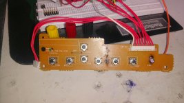
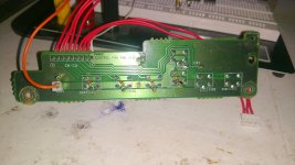
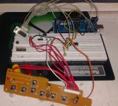
I know I'm a newbie.lol any way I made my button pad froman old NEC tube monitor it had extra buttons to boot. I only had to solder the resisters on the back of the board. Here the Front and back pictures of the one I made. Hope to get my arduino mega up and running soon!!!I'm going to make my wires much nicer,I'm going to make a cable.As you will see. the wires are everywhere. I want to get it to work first.Everything I used to make my button pad and monitor plug was from old computer parts even the resistors are used from an old toshiba calculator that I desoldered every electronic part that was on the board.
typo 1:int fad = 6; / Original volume for the fader set to 6 initial setup when sub
turned on
Correction: int fad = 6;// etc.......just that one symbol.lol
typo 2:int cent = 6;/ Original volume for the Center set to 6 initial setup when sub
turned on
Correction: int cent =6:// etc....same typo.
It took me some time because when it told me the error I didn't even understand it. It was greek to me. So I looked at the code and noticed that these 2 lines were different then the rest. Look for yourself.After I fixed them the error where gone.It told me line 45 & 46: error: expected unqualified-id before '/' token
int select = 0;// 0 volume, 4
int vol = 80;//original 80 for test 30
int sub = 82;// Original volume for the sub set to 82 initial setup when sub
turned on
That's how I noticed it by comparing it to the rest of the similar code lines.
I know I'm a newbie.lol any way I made my button pad froman old NEC tube monitor it had extra buttons to boot. I only had to solder the resisters on the back of the board. Here the Front and back pictures of the one I made. Hope to get my arduino mega up and running soon!!!I'm going to make my wires much nicer,I'm going to make a cable.As you will see. the wires are everywhere. I want to get it to work first.Everything I used to make my button pad and monitor plug was from old computer parts even the resistors are used from an old toshiba calculator that I desoldered every electronic part that was on the board.
Attachments
So I got it working Kind of.The scl and sda lines have a 5k resistor in series of each connection and when connected to arduino it wont let the arduino turn on or do anything. when not connected to the vga connector it works fine and sends the code. I verified the code being sent with the monitor function of the arduino program. so here is where I am. I took mute and stby to ground and power it up. I also had to bypass the 5k resistors and connected straight to scl and sda pins and it lets the arduino send the commands but when I turn it all on and push the power button on the arduino nothing. Ity only turns on after I PUSH THE VOLUME BUTTON TO UP THEN IT WORKS. THE VOLUME IS CLOSE TO ALL THE WAY maybe little more then half way. I'm not sure cause I never heard it working. I found this unit from dumpster diving.
Update: I have gotten it to work!!!!! It works Great!!Sounds Great. All the buttons work as described!! My only issues I have had.
To get it to work correctly I had to use the original Twi.h file. when I changed the nack and ack code lines and reverse the numbers it made it not work right. After changing the values it worked like it said it would if you didn't change them.So for me the non modified twi.h file worked for me and I could never get it to work with the 5k smd resisters on the amp board in series of the sda and scl lines. I had to solder a wire over each resister and bypass them. That aloud me to use the monitor control plug and not have to solder to the IC sda and scl pins. the wire was the easist way to do it for me.So if you have any issues like I had try what I did. It works great!!!!
Now for my next road block. I'm lost too. I want to write the code to control the Bass and treble. I have no idea how to take hex code from the data sheet and turn it into a i2c sketch for my arduino.If there is anybody out there that knows Please Help. I hope My post will contribute to this thread. I can say it works!!!And is real easy to do.
P.s Also when you hook your grounds up make sure you use 3 grounds. The 3 are at the monitor plug pin 1,7,8.
Pin 1 to the main ground where you hook the 5v up on the arduino.
Pin 7 to the gnd on the arduino next to the sda and scl connections
Pin 8 to the gnd for your buttons then from that point run another wire to another gnd spot on your arduino.
Its over kill I know but it assures a good gnd connection that you need for the sda and scl lines to work well.
I have gotten it to work!!!!!
Glad this helped you!
Apparently there are several Hardware version on the market Logitech may have change components or program during the whole product lifecycle.
I did that work last year and since then I made a Remote control receptor that the YV remote controls. I used an Arduino Nano to minimize the board size and put a simple IR instead of button. It is better not to have to stand up to change the volume
")
Be careful if you want to make a clean board and create a remote with a VGA cable there are VGA cable that are combining the GND of the color channels and that doesn't work with the remote setup. That is the reason why it is said not to use extender in the back of the Unit.
Regarding the Bass and Trebble, I'm not sure that this product has the capacity to adjust the spectrum. I was in the impression that the bass is simply managed by the level of the Sub. Maybe by looking at the datasheet of the controller inside the Sub you could find some details but I have my doubt.
For sure it's an old topic
But I just found a Z5300 a few days ago for just 15 $ CAD.
Thanks a lot to Rem604 for the code !
I didn't modify the Wire library, but soldered the pins to the external connector.
I'm currently using a modified code from Rem604's.
I prefere using a rotary encoder then 2 push buttons.
I also modified the code to store settings in the Arduino EEProm.
Nothing too difficult ...
But I have a problem with the "select" button.
The initial behavior is to switch between sub, center and fader.
I want to add balance, since it's just a need for me.
I ear quite correctly with my left ear, note so much with the right.
So the way I balance between sides is important for me, even if for most of people it may seems odd
In the original code, the first i2c is to select which function is used. The second i2c frame send the value.
I can't understand how the "select" mode works, and change between 4, 7, 0 or whatever ...
Any help will be nice.
I've modified the code for my own use, it's ugly and I don't care.
If some are interested, I'll make a clean version and a pcb with Kicad.
C:
// Start Code Arduino Sketch Z-5300 SoundTouch Wired Remote Control.

// NonaSuomy


// 1. GND

// 2. Headphones 1

// 3. GND

// 4. Headphones 2

// 5. GND

// 6. +5V power to remote

// 7. GND

// 8. GND

// 9. GND

// 10. Not connected (I think so)

// 11. STBY command from remote to the system

// 12. MUTE command from remote to the system

// 13. Spatial stereo command from remote to the system

// 14. I2C SCL from remote to system (NJW1150)

// 15. I2C SDA from remote to system (NJW1150)


// 12 Pin Header to VGA

// |010305070911|

// |020406081012|

// Header > VGA

// 01 > 01

// 02 > 02

// 03 > 03

// 04 > 04

// 05 > 05

// 06 > 06

// 07 > 07

// 08 > 15

// 09 > 14

// 10 > 13

// 11 > 12

// 12 > 11


// Arduino > Part

// 02 > Encoder A

// 03 > Encoder B

// 06 > 10 Pin Header > VGA 13

// 07 >

// 08 > Encoder Button

// 09 > 12 Pin Header > VGA 11

// 11 > IR Receiver

// 18 A4(SDA) > 08 Pin Header > VGA 15

// 19 A5(SCL) > 09 Pin Header > VGA 14


#include <Wire.h>

#include <IRremote.h>

#include <Encoder.h>


// Code Shield Pinout.

#define ENCODER_A 2

#define ENCODER_B 3

#define MATRIX 6

#define SERVO 7

#define BUTTON 8

#define SWITCH 9

//#define ENCODER_A 14

//#define ENCODER_B 15

//#define ENCODER_PORT PINC

//#define SWITCH 13

//#define BUTTON 12

#define RGB_RED 4

#define RGB_GREEN 10

#define RGB_BLUE 12

#define LED 13

//#define SERVO 4

//#define PIEZO 3

//#define RELAY 2

//#define POT 2

//#define HALL 3

//#define THERMISTOR 4

//#define PHOTOCELL 5


// Volume Controls.

int standbyPin; // = SERVO;

int mutePin; // = SWITCH;

int matrixPin; // = MATRIX;

int selectPin = BUTTON;

int powswiPin = 5; //= SWITCH;

//int standbyPin = SWITCH;

// Colour Pins.

int redPin = RGB_RED;

int greenPin = RGB_GREEN;

int bluePin = RGB_BLUE;

int whitePin = LED;


// Tell IRremote which Arduino pin is connected to the IR Receiver (TSOP4838).

int recvPin = 11; // Arduino pin the IR receiver is attached to.

IRrecv irrecv(recvPin); // Enable IR pin.

decode_results results; // Create instance of 'decode_results'.

unsigned long lastCode; // Store last code sent, in case of repeat code.


// 7 LED's for volume indication.

class irCodes {

  public:

    enum Constants {

      irVolUp = 0xFF7887, // 16742535 Volume Up.

      irVolDown = 0xFF50AF, // 16732335 Volume Down.

      irMode = 0xFF2AD5, // Volume, Sub, Fader, Center. 4 LED's for mode indication.

      irMute = 0xFF6897, // Mute.

      irPower = 0xFFB24D, // Power.

      irMatrix = 0xFF30CF // On/Off. 1 LED for power indication.

    };

};


// Hold volume control data in a multidimensional array.

// CurrentValue,MinValue,MaxValue,Red,Green,Blue.

int mem[][6]={

  // 00 VOL : Volume control for all channels (1dB/step)[00000000]0dB to -79dB[1001111], Default Value: MUTE[1010000].

  //          Maximum Attenuation: Master Volume: -79dB, Trimmer: -20dB.

  //          Minimum Attenuation: Master Volume:   0dB, Trimmer:   0dB.

  {50,0,80,80,0,80}, // VOL

  // 01 L-BAL : Balance control for Left channel (1dB/step) [00000]0dB to -30dB[11110], MUTE[11111].

  {0,0,31,0,255,255}, // LBAL

  // 02 R-BAL : Balance control for Right channel (1dB/step) [00000]0dB to -30dB[11110], MUTE[11111].

  {0,0,31,0,0,255}, // RBAL

  // 03  C TRIM :Volume Center Channel Trimmer Control ([00000]0dB to -20dB[10100] Default Value: -10dB[01010]).

  {10,0,20,255,255,0}, // CTRIM

  // 04 SL TRIM :Volume Surround Left Channel Trimmer Control ([00000]0dB to -20dB[10100] Default Value: -10dB[01010]).

  {10,0,20,0,255,0}, // LTRIM

  // 05 SR TRIM :Volume Surround Right Channel Trimmer Control ([00000]0dB to -20dB[10100] Default Value: -10dB[01010]).

  {10,0,20,255,0,0}, // RTRIM

  // 06 SW TRIM :Volume Sub Woofer Channel Trimmer Control ([00000]0dB to -20dB[10100] Default Value: -10dB[01010]).

  {10,0,20,255,0,255}, // WTRIM

  // 07 TONE CONTROL ([11011101]+10dB to -10dB[01010101]).

  //    TREBLE      BASS

  //    D7 D6 D5 D4 D3 D2 D1 D0

  //    1  0  0  0  1  0  0  0  {10001000}

  {0,0,79,255,255,255}, // TONE.

  // 08 MUTE CONTROL (0=OFF 1=MUTE).

  {1,0,1,0,0,0} // MUTE.

};


// Button debounce variables.

int buttonState = LOW; // Tracks the state of the button, low if not pressed, high if pressed.

long lastDebounceTime = 0;  // Last time the output pin was toggled.

long debounceDelay = 250;    // Debounce time; increase if the output flickers.


// Button current value selected.

int selectState = 0; // Tracks the state of the select command.

int stateSelectLast = 0; // Track the last state of the select command.


// Encoder Stuff.

// Change these pin numbers to the pins connected to your encoder.

// Best Performance: both pins have interrupt capability.

// Good Performance: only the first pin has interrupt capability.

// Low Performance:  neither pin has interrupt capability.

// Avoid using pins with LEDs attached.

Encoder EncKnob(ENCODER_A, ENCODER_B); // Generate Encoder EncKnob.

long EncPosition  = -999; // Define encoder starting position.

long newENC; // Capture new encoder position.


// Setup our microcontroller.

void setup() {

  // Start I2C;

  Wire.begin();

  // Start serial for debugging.

  Serial.begin(9600);

  irrecv.enableIRIn();  // Start the receiver.

  // These two pins require to be put to the ground in order for the unit to turn on.

  standbyPin = SERVO;

  mutePin = SWITCH;

  // Configure Remote other buttons.

  pinMode(standbyPin,OUTPUT);

  pinMode(mutePin,OUTPUT);

  pinMode(matrixPin,OUTPUT);

  // Make sure the power is off before starting control.

  Serial.println("Power Off");

  digitalWrite(standbyPin,HIGH);

  digitalWrite(mutePin,HIGH);

  // Turn power on to unit.

  Serial.println("Power On");

  digitalWrite(standbyPin,LOW);

  digitalWrite(mutePin,LOW);

  digitalWrite(matrixPin,HIGH);

  // Configure colour LED.

  pinMode(redPin,OUTPUT);

  pinMode(greenPin,OUTPUT);

  pinMode(bluePin,OUTPUT);

  pinMode(whitePin,OUTPUT);

  // Hardware remote buttons.

  pinMode(selectPin,INPUT);

  pinMode(powswiPin,INPUT);

  // Send I2C command to unmute the system, as it starts up muted.

  Serial.println("UNMUTE");

  i2cmd(0,80);

  i2cmd(8,0);

  // Write the initial volume state to the active encoder position.

  EncKnob.write(mem[selectState][0]);

}

// Send I2C commands to NJW1150.

void i2cmd(int cmd, int val) {

  Wire.beginTransmission(0x44); // Send I2C command to NJW1150's default address.

  Wire.write(cmd); // Item to control.

  Wire.write(val); // Value to set to.

  Wire.endTransmission(); // Send data via I2C.

  Serial.print("CMD: ");

  Serial.print(cmd);

  Serial.print(", Value: ");

  Serial.println(val);

}

// Change colour of the LED to show the state we are in for sending commands to NJW1150.

void setColor(int red, int green, int blue) {

  #ifdef COMMON_ANODE

    red = 255 - red;

    green = 255 - green;

    blue = 255 - blue;

  #endif

  analogWrite(redPin, red);

  analogWrite(greenPin, green);

  analogWrite(bluePin, blue);

}

// Main Programming Loop.

void loop() {

  if (irrecv.decode(&results)){ // Received an IR signal?

    if(results.value != 0xFFFFFFFF){ // Receive a code that is repeated: 0xFFFFFFFF

      lastCode = results.value; // Store last code value.

    }

    {

    switch (lastCode){

      case irCodes::irVolUp: // Volume UP button pressed.

        Serial.print("irVolUp ");

        Serial.print("Real Value: ");

        Serial.println(results.value, HEX);

        Serial.print("Repeated Value: ");

        Serial.println(lastCode, HEX);

      break;

      case irCodes::irVolDown: // Volume DOWN button pressed.

        Serial.print("irVolDown ");

        Serial.print("Real Value: ");

        Serial.println(results.value, HEX);

        Serial.print("Repeated Value: ");

        Serial.println(lastCode, HEX);

      break;

      case irCodes::irMode: // Mode button pressed.

        Serial.print("irMode ");

        Serial.print("Real Value: ");

        Serial.println(results.value, HEX);

        Serial.print("Repeated Value: ");

        Serial.println(lastCode, HEX);

      break;

      case irCodes::irMute: // Mute button pressed.

        Serial.print("irMute ");

        Serial.print("Real Value: ");

        Serial.println(results.value, HEX);

        Serial.print("Repeated Value: ");

        Serial.println(lastCode, HEX);

      break;

      case irCodes::irPower: // Power button pressed.

        Serial.print("irPower ");

        Serial.print("Real Value: ");

        Serial.println(results.value, HEX);

        Serial.print("Repeated Value: ");

        Serial.println(lastCode, HEX);

      break;

      case irCodes::irMatrix: // Matrix button pressed.

        Serial.print("irMatrix ");

        Serial.print("Real Value: ");

        Serial.println(results.value, HEX);

        Serial.print("Repeated Value: ");

        Serial.println(lastCode, HEX);

      break;

    }

    Serial.print("Debug All IR Values: ");

    Serial.println(results.value, HEX);

    irrecv.resume(); // Receive the next value.

  }

  delay(1000);

  }

  // Sample the state of the button.

  buttonState = digitalRead(selectPin);

  // Filter out any noise by setting a time buffer.

  if ( (millis() - lastDebounceTime) > debounceDelay) {

    // If the button has been pressed.

    if (buttonState == HIGH) {

      selectState ++;

      lastDebounceTime = millis(); // Set the current time.

      // Reset count if over max mode number.

      if(selectState > 8) {

        selectState = 0;

      }

      // Configure the encoder with the value from memory before changing control.

      EncKnob.write(mem[selectState][0]);

    }

  }

  // Check if the encoder has changed its position from the last time or state select (LED Colour update workaround).

  newENC = EncKnob.read();

  if ( newENC != EncPosition || stateSelectLast != selectState ) {

    EncPosition = newENC;

    Serial.print("ENC = ");

    Serial.print(newENC);

    Serial.println();

    // NJW1150 6 Channel Electronic Volume Control.

    // 6-Chnnel Master Volume 0 to ?79dB, MUTE.

    // Balance control for L, R-ch 0 to ?30dB, MUTE.

    // Trim Level Control for C, SL, SR, SW-ch 0 to ?20dB.

    // Independent Tone Control (Bass, Treble) for L, R-ch.

    // I2C Control Command.

    Serial.print("State: ");

    Serial.println(selectState);

    // Set LED colour to show which item in the mode select the control is at (Red = Vol, etc).

    setColor(mem[selectState][3], mem[selectState][4], mem[selectState][5]);

    // Reset encoder to prior value if above the max of volume processor.

    if (newENC > mem[selectState][2]) {

      Serial.print("Reset encoder to highest value allowed ");

      Serial.println(mem[selectState][2]);

      EncKnob.write(mem[selectState][2]);

    }

    // Reset encoder to prior value if above min of volume processor.

    else if (newENC < mem[selectState][1]) {

      Serial.print("Reset encoder to lowest value allowed ");

      Serial.println(mem[selectState][1]);

      EncKnob.write(mem[selectState][1]);

    }

    mem[selectState][0] = newENC; // Update mem variable with current encoder value selected.

    i2cmd(selectState,newENC); // Send I2C command with updated encoder value to NJW1150.

    stateSelectLast = selectState; // Track last select state change.

  } // Encoder Change.

} // Loop.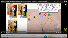
- Home
- Amplifiers
- Chip Amps
- Logitech Z-5300 without remote