I've bought some time ago this PCBs for LM1875 chips but I dont't have a scheme for this circuit. Could anyone help me? In application note there's nothing similar.
They are places for eight diodes, two electrolitic capacitors and three resistors. What value of these parts to use?
Top side:
They are places for eight diodes, two electrolitic capacitors and three resistors. What value of these parts to use?
Top side:
Attachments
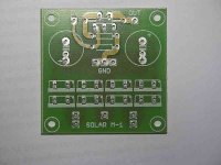
Yes, there is. The place of the uppermost resistor in your photo is for R4, directly below the IC there is R3 and below that R2. The capacitors are C6 and C7, all derived from the first page of the datasheet.missieek said:In application note there's nothing similar.
As you can see, the datasheet shows more components. All of them have their purpose. Most of them have to do with safety.
Your PCB is the minimum configuration that is able to work at all. On your PCB there is no blocking at the input that could protect the IC from dangerous signals. Neither is there a Zobel circuit at the output to prevent the amp from oscillating. DC protection is also not provided on board.
Conclusion: If you use it at all, use it only with a small power supply and a robust speaker to bring the potential for damage down. Or add all the missing components off board.
- Status
- This old topic is closed. If you want to reopen this topic, contact a moderator using the "Report Post" button.