Hello -
I have a simple power supply consisting of an older 15V dual primary toroid.
Two black wires go to A/C, Red, Yellow, Blue, Grey (Yellow/Blue tied together), Yellow and Grey going across a Diode bridge made of Mur 160 diodes into a 4700uf 50V cap per rail. From my DMM on the positive side with Black lead on Ground and Red lead on Plus I measure 36V. From Black side on Negative and Red side to Ground I measure 36V. (Not sure if I am measuring this correctly)
On positive side I have an LM337 working correctly with a 240ohm resistor as r1 and 2700 as r2. I measure -15.3 at the output. The positive side has an LM317 Same resistors wired with AOI unlike AIO on the working LM337. On the first LM317 I broke the leg. On the second I got no voltage output. On the thrid LM317 I blew the 1/2A fuse. I replaced the fuse with a 1A which my circuit required anyway. Retesting the third LM317 it popped and cracked in half.
What is wrong could be wrong with the positive side?
Mike
Sounds as if you have wired the secondries of the power supply together in series basically doubling up the 15v rails.
I woud recommend you untie the two secondries and use two recifiers to give you +/- on one secondry, +/- on the other.
You then take tie the recified - from one and the rectified + of the other to form a ground. This will give you sufficient voltages to run the lm317 and 337 hopefully without further mishap.
I can find a diagram when I get home if you need it.
djmike said:
On positive side I have an LM337 working correctly (...)
I measure -15.3 at the output.
(...)
Black side on Negative and Red side to Ground I measure 36V.
(...)
(Not sure if I am measuring this correctly)
Hi Mike,
Sorry, your explanation is not very clear (see quoted portions).
The pinouts you give for LM3x7 are correct, but you say you have 337 on positive... is this a typo?
(I'm too lazy now to think myself if and how a 337 may survive on "positive" and not a 317 on "negative"...)
Also the transformer and DMM cables colors are hard to follow...
And why do you say "dual primary"?
Are the dual secondaries supposed to be 15V-AC?
Of course make sure that the secondaries are fine: that is you have the same AC on the two referred to "ground" (you call "ground" the yellow-and-blue-tied-together, right?)
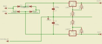
At the end your circuit seems to look like the schematic attached (sorry, drew it in a hurry).
Let me say already that he suggestion by justblair, to use separate rectifier bridges and regulators, allows you to drop 22V to 15.3V, and is more more reasonable.
If the circuit is like that, you should measure the following:
keep the DMM-common (black cable) always on GND, and putting the DMM-red cable on the indicated points you must get:
- The same AC value (DMM in AC mode!) on "RED" and "GRAY" (15V AC?)
- About +42V DC (so DMM in DC mode) on the plus of C1
- About -42V DC on the MINUS of C2 (whose plus goes to GND)
- 15.3V DC positive and negative on the output of the regulators.
(and a very hot regulator, dropping 30V times your current
 )
)Again, all these values are referred to GND, which is YEL+BLUE.
Only correct if those are indeed the two secondaries in series (which makes it a "center-tapped secondary").
Hope this is clear.
But post your schematic, so we can check it out.
Cheers.
EDIT: I noticed that some details of the schematic went lost in JPEG translation.
"OW" on the bottom left should read "YELLOW".
The capacitors BOTH have the plus-leg "upwards", that is C1 on the positive rail has the plus-leg on the rail, and minus-leg on GND; whereas C2 on the negative rail, has plus-leg on GND and minus-leg on the negative rail. This is important (but then the caps would have popped, not the regulator...)
_
Attachments
djmike said:
Two black wires go to A/C,
Red, Yellow, Blue, Grey (Yellow/Blue tied together),
Yellow and Grey going across a Diode bridge
(...)
...Mike,
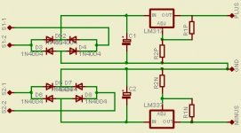
looking more carefully, your connections have something worrysome.
As justblair suggested, undo the four secondary wires, and with the transformer UNPLUGGED, identify the two secondaries: with the DMM on resistance mode (ohm-meter) on the lowest scale, measure the cables two by two. Those pairs that have low resistance ("non-infinite") are the two secondaries.
Once you have these, wire up as in this attachment, where I indicated S1 and S2 for the two secondaries.
Cheers.
_
Attachments


Piltron update
Hello -
The two black wires are inifite and are wired to 120 (primary).
The dual secondary is Blue and Grey 3.4 ohm and Red and Yellow 3.4 ohm.
The transformer is Piltron 1A15 marker 22v 0 22v, which came with the original Sultzer Borbely SB1 years ago and ran fine with 15v output wired with
the center tied together.
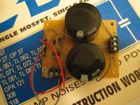
My diagram exactly matches Pilli's schematic. I have the LM317 and LM337 screwed to the steel case. If someone can show me how to fix my post I can fix the photos so they show up rather than the HMTL image code.
I can rewire the breadboard with a pair of kbl005 7628 Bridge rectifiers but I don't think that is going to change the 30V drop the rectifiers are facing. The LM317 is rated at 40V drop. Why is the positive side popping and how should I keep the transformer and keep the power supply stable? I'm willing to change the resistor values so that 18Volt is what will be presented to the Didden Jung regulator in the photo (Which I dare not hook up until this is solved).
Again - seeing the photos would help greatly so if someone can tell me how to fix my posting so the image show up that would help.
Mike
Hello -
The two black wires are inifite and are wired to 120 (primary).
The dual secondary is Blue and Grey 3.4 ohm and Red and Yellow 3.4 ohm.
The transformer is Piltron 1A15 marker 22v 0 22v, which came with the original Sultzer Borbely SB1 years ago and ran fine with 15v output wired with
the center tied together.
My diagram exactly matches Pilli's schematic. I have the LM317 and LM337 screwed to the steel case. If someone can show me how to fix my post I can fix the photos so they show up rather than the HMTL image code.
I can rewire the breadboard with a pair of kbl005 7628 Bridge rectifiers but I don't think that is going to change the 30V drop the rectifiers are facing. The LM317 is rated at 40V drop. Why is the positive side popping and how should I keep the transformer and keep the power supply stable? I'm willing to change the resistor values so that 18Volt is what will be presented to the Didden Jung regulator in the photo (Which I dare not hook up until this is solved).
Again - seeing the photos would help greatly so if someone can tell me how to fix my posting so the image show up that would help.
Mike
Click the IMG button above the Your Reply field. You need to either disable your pop-up blocker for that or allow the script temporarily.
Another method is to use the Attach File function below the Your Reply field. Click on search and select the image file you want to show. The image file size is however limited.
Another method is to use the Attach File function below the Your Reply field. Click on search and select the image file you want to show. The image file size is however limited.
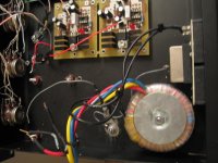
I have the LM317 and LM337 screwed to the steel case. I
That's the problem. The tags on the regulators are electrically tied to the centre pin. That puts a short on the 317 since its output is now tied to the input of the 337.
The regulators must be on insulated heatsinks, or insulated from the heatsinks with a mica washer and plastic bush.
Steerpike said:There is really no need for two rectifier bridges.
Steerpike is right, it all works well with one bridge.
(Anyway he found the real problem, so that's the good thing.)
But my earlier post (number 5) is wrong
 , the rectified voltages of the rails, referred to ground/center tap (that's what the capacitors have) are not what I stated, but half of that, so there is no risk of overheating.
I'm posting this just in case somebody finds this thread...
maybe some moderator should remove that misleading post, or correct the 42V to 21V?
Sorry...

I promise you: I've built and measured several of these, they make my music play, but somehow I got mislead...
- Status
- This old topic is closed. If you want to reopen this topic, contact a moderator using the "Report Post" button.
- Home
- Amplifiers
- Chip Amps
- LM317/Power supply help?