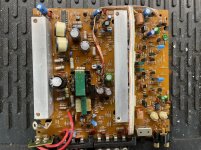
This is made in Korea. Looks more like an Alpine than anything else. Single sided PCB. NOT a Zed Audio amp by any means. Board is stamped Nakamich B3xx.
It will not power up and no major components seem shorted. The 494 is outputting saw-tooth and 5v.
494
1: 0.024
2: 0.011
3: 4.88
4: 1.633
5: 1.703
6: 3.639
7: 0
8: 14.43
9: 0.031
10: 0.011
11: 14.43
12: 13.51
13: 5.04
14: 5.04
15: 5.04
16: 0
Is something driving pin 3 too high? Its connected to many components throughout the amp.
Last edited:
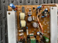
On the board,
These are closer to the speaker terminals.
R423 is a 470o resistor measuring OK
R425 is a 6.7k measuring OK off the board and 4.7k on the board
Referencing the schematic|board,
R423|R443 measuring 10k off, and 5k on the board This is between 494 pin 2 and 7
R425|R444 ^ ^^ Same. This is between 494 pin 2 and 14+ more
Last edited:
I removed Q121. The amp powered up and seems like it has clean signal on speaker terminals though I did not supply a load. Just with my frequency generator and scope.
Q121 testing OK out of circuit. It connects to LOTS of other components
494 pins are both at 1.9vDC like this.
Q121 testing OK out of circuit. It connects to LOTS of other components
494 pins are both at 1.9vDC like this.
Q121 isn't properly represented on the diagram. Its a 2sc2785 and it's collector is DIRECTLY connected to Pin2 of the 494.
The closest on the diagram is Q422 but thats a different transistor and through an 18k (R458-D). Not the same as this amp does not have a resistor like R458-D in series, however Q121's emitter is definitely connected through resistors and such to pins 6/7 at least of the 494.
The closest on the diagram is Q422 but thats a different transistor and through an 18k (R458-D). Not the same as this amp does not have a resistor like R458-D in series, however Q121's emitter is definitely connected through resistors and such to pins 6/7 at least of the 494.
Last edited:
Q121's base is connected to a LOT of other components, not totally like the diagram. The diagram shows a stereo/mono switch but this amp doesn't have that. I'd say the BASE of Q121 (Q422-D) is connected sort of similarly to Q420 but without a switch in front of it. Maybe not exactly though as it gets further from the schematic the more I go. It gets busy pretty quickly.
I began tracing back from Q121 to each level of component. Removal of some made the amp power on, but some parts removed far down the line would make the amp clip very very badly inputting a sine wave and 4-ohm load at very low voltage/draw. If I remove Q121 completely the amp plays and shows clean on my scope up to clipping and pulls about 13A from my power supply under a 4-ohm load per channel - almost acting fixed.
I have my suspects about a component, C114 ESY. Seems to be the following data sheet.
http://www.farnell.com/datasheets/26011.pdf
I sensed R1 and R2, but am I supposed to be able to diode-test with my meter from Out-Gnd? Its not measuring anything at all.
I have my suspects about a component, C114 ESY. Seems to be the following data sheet.
http://www.farnell.com/datasheets/26011.pdf
I sensed R1 and R2, but am I supposed to be able to diode-test with my meter from Out-Gnd? Its not measuring anything at all.
- Status
- This old topic is closed. If you want to reopen this topic, contact a moderator using the "Report Post" button.
- Home
- General Interest
- Car Audio
- Nakamichi PA-202