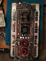
Just picked up a PPI Tube amp and it’s showing DC offset in the right channel, positive outputs (circled in red) are driven to rail and relays will not engage as a result. I don’t have any documentation for this amplifier, but the outputs appear to be driven by a small collection of discrete transistors underneath the vacuum tubes. A few of those look to have been replaced in the past, so I suppose I’ll start there. Any help would be appreciated.
Attachments
Finally had the opportunity to put some serious time into this amplifier, I learned a lot about its design.
I discovered more trouble upline from the output stage and tubes, namely the TO-220 cased regulator transistors which were mostly fried as were several smaller TO-92 cased ones nearby which form the control circuits for those same regulators. There was also a cold solder joint on a filter cap on the output side of the high voltage regulators, it was only held into the board by one leg. This likely got missed by previous repair attempts (and clearly there have been several as we will see below), since the pads for it are obscured on the bottom of the PCB by the DC protection board which was hot glued right over the area.
I think what happened was the cap caused an intermittent connection that caused the regulator to die, which after shorting out caused full high voltage to be sent downstream to all the stages connected to it. That’s what killed the 4 diodes I found earlier, one of the output stage driver transistors and most of the regulator control circuitry.
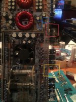
In the picture I highlighted the high voltage regulators in red, control transistors in blue and output stage drivers yellow. All of these were confirmed shorted, and removed from the board.
This is a fairly sophisticated amplifier- there is a turn on delay while the tubes warm up, after which the main power supply begins operation. There are 3 completely separate supplies: filament, which appears to come right off the 12v input since the tubes warm up before the power supply FETs start switching. Once the main supply begins operation +/-40vdc is provided to the output stage transistors as would be the case for any other transistor amplifier, but there is an additional set of windings to provide high voltage to run the tubes. This goes through a full wave rectifier consisting of 4 DO-14 packaged units, then a set of filters, and on to the MJE15033 and MJE15032 regulators. After the regulators there is a bit more filtering, then it heads on over to the SV83 tubes. The tubes themselves seem to be run in pentode mode, not triode mode as I originally assumed.
Anyhow this amplifier has been repaired before. I know this because most of the devices were made by Sanken, but the drivers in the output stage aren’t matched anymore. One is a 2SD2400, meaning the other should be a 2SB1569 or something like that but instead it had a TIP50 in place. Additionally one of the regulators has been replaced with a 2N6488. There are also various house marked TO-92 case transistors smattered around the board, since I can’t verify their ratings they will be replaced.
I need to finish combing the board for bad silicon and make another order, hopefully then ill have something positive to report.
I discovered more trouble upline from the output stage and tubes, namely the TO-220 cased regulator transistors which were mostly fried as were several smaller TO-92 cased ones nearby which form the control circuits for those same regulators. There was also a cold solder joint on a filter cap on the output side of the high voltage regulators, it was only held into the board by one leg. This likely got missed by previous repair attempts (and clearly there have been several as we will see below), since the pads for it are obscured on the bottom of the PCB by the DC protection board which was hot glued right over the area.
I think what happened was the cap caused an intermittent connection that caused the regulator to die, which after shorting out caused full high voltage to be sent downstream to all the stages connected to it. That’s what killed the 4 diodes I found earlier, one of the output stage driver transistors and most of the regulator control circuitry.
In the picture I highlighted the high voltage regulators in red, control transistors in blue and output stage drivers yellow. All of these were confirmed shorted, and removed from the board.
This is a fairly sophisticated amplifier- there is a turn on delay while the tubes warm up, after which the main power supply begins operation. There are 3 completely separate supplies: filament, which appears to come right off the 12v input since the tubes warm up before the power supply FETs start switching. Once the main supply begins operation +/-40vdc is provided to the output stage transistors as would be the case for any other transistor amplifier, but there is an additional set of windings to provide high voltage to run the tubes. This goes through a full wave rectifier consisting of 4 DO-14 packaged units, then a set of filters, and on to the MJE15033 and MJE15032 regulators. After the regulators there is a bit more filtering, then it heads on over to the SV83 tubes. The tubes themselves seem to be run in pentode mode, not triode mode as I originally assumed.
Anyhow this amplifier has been repaired before. I know this because most of the devices were made by Sanken, but the drivers in the output stage aren’t matched anymore. One is a 2SD2400, meaning the other should be a 2SB1569 or something like that but instead it had a TIP50 in place. Additionally one of the regulators has been replaced with a 2N6488. There are also various house marked TO-92 case transistors smattered around the board, since I can’t verify their ratings they will be replaced.
I need to finish combing the board for bad silicon and make another order, hopefully then ill have something positive to report.
Attachments
Last edited:
Having a little trouble identifying replacements for the driver transistors, there don't seem to be anything suitable in a TO-220 package and the ones I do find that might be close are NLA. Can I get a hint lol?
Originally it had 2SD2400/2SB1569 (TIP50 was in place of the 2SB1569), which is 160v, 1.5A, Hfe around 150 or so.
Originally it had 2SD2400/2SB1569 (TIP50 was in place of the 2SB1569), which is 160v, 1.5A, Hfe around 150 or so.
You don’t think the lowish Hfe will be a problem? The originals were between 100 and 200 according to the data sheet, those MJE’s say minimum 40 but nothing else. Assuming it doesn’t matter much, since the drivers are typically arranged as followers implying unity gain anyway?
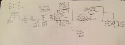
I made a diagram of the regulator circuit, sorry for my crappy skills. Have a look, see if it makes any sense?
I made a diagram of the regulator circuit, sorry for my crappy skills. Have a look, see if it makes any sense?
Attachments
Turns out the output stage is indeed correct, I popped the cover off my TD275 and the layout is identical to this one just with one less output transistor. So I guess the 2SD2400/TIP50 combination is how it was from the factory. Last of the replacement parts should be here in the coming week, keeping my fingers crossed!
Last of the replacement parts have been installed so I put the board back into the sink and gave it power, it came up and idled at 4.8A which doesn’t sound too horrible and nothing blew up far as I can tell. But one channel is railed negative, the other railed positive and the relays remain open.
- Status
- This old topic is closed. If you want to reopen this topic, contact a moderator using the "Report Post" button.
- Home
- General Interest
- Car Audio
- PPI Tube Driver TD2150