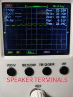
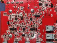
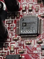
Have a Kicker KX800.1 here that powers up, but has no output at the speaker terminals. It has 64v or rail at the rectifier, 32v at each output inductor and speaker terminals, and ±15.6v from the regulators. The input signal makes it to the NJM2068 on the bottom of the board so the input board is good. The difficulty with this amp is that I am afraid to power it up without it bolted down to the chassis as I worry that the FETs and outputs may overheat. With most of the circuitry on the bottom of the board, I have been soldering wires to the various test points and reassembling to power up. If idling out of the chassis is not a problem then that would make it easier but with the amount of current it pulls to power up, I am concerned.
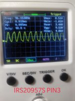
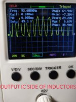
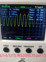
I am posting scope shots of IRS20957s PIN3, and output inductor input and output. I do not have a square wave going into the output inductor.
I am posting scope shots of IRS20957s PIN3, and output inductor input and output. I do not have a square wave going into the output inductor.
Attachments
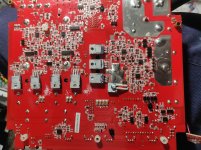
You can operate outside the chassis, of course without a load.
The voltage on inductors would indicate drive, not sure why your not seeing on scope.
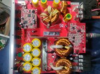
Once I have a chance to look at schematic I can advice further. Pics would be helpful once you have the board outside chassis
The voltage on inductors would indicate drive, not sure why your not seeing on scope.
Once I have a chance to look at schematic I can advice further. Pics would be helpful once you have the board outside chassis
Scope shots with DSO Shell. Not sure if it is able to display a 100khz square wave. Going to try with the OWON and repost.
Attachments
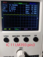
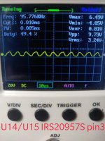
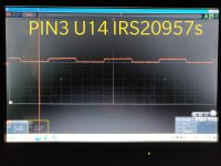
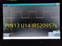
So, I guess the DSO is not able to display a proper square wave at 100khz. Scope shots of PIN3 and PIN13 of U14 and U15 IRS20957S. So I assume the amp is working properly according to the these measurements, but the audio is not making it all the way through the amp. How do I find the disruption?
It was mentioned in another post that the 10ohm resistor connecting the speaker - terminal to the GND input terminal would engage the muting transistors if it is defective or missing, caused by DC offset. Could this be what is occurring in this amp. With the ohmmeter set on AUTO, testing between speaker - and GND input reads 600+ ohms and rising past 900 ohms and continues ranging upwards.
It was mentioned in another post that the 10ohm resistor connecting the speaker - terminal to the GND input terminal would engage the muting transistors if it is defective or missing, caused by DC offset. Could this be what is occurring in this amp. With the ohmmeter set on AUTO, testing between speaker - and GND input reads 600+ ohms and rising past 900 ohms and continues ranging upwards.
Attachments
Last edited:
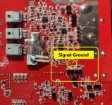
This is an H bridge output configuration. Neither speaker terminals are grounded.
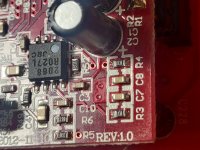
Measuring between Signal (Transformer secondary center tap-Pic Attached) and Power grounds should be zero ohms. Even if R35 is high or open the measurement will be low. Lift R35-10 ohm and check with ohmmeter to be sure.
If this all checks out, you will need to signal trace trough the preamp
Measuring between Signal (Transformer secondary center tap-Pic Attached) and Power grounds should be zero ohms. Even if R35 is high or open the measurement will be low. Lift R35-10 ohm and check with ohmmeter to be sure.
If this all checks out, you will need to signal trace trough the preamp
Attachments
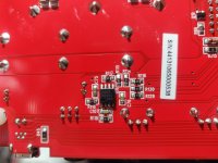
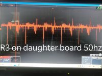
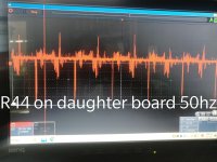
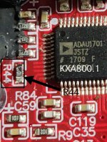
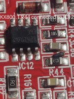
On this amp, R44 is on the main board connected to pin5 of IC12 LM393. R3 and R4 are on the daughter board. In the 44KXA800.1, which I will be posting to repair as soon as this one is fixed, R44 is on the daughter board. This pic is from the RCA input board.
Attachments
Last edited:
On this amp, R44 is on the main board connected to pin5 of IC12 LM393. R3 and R4 are on the daughter board. In the 44KXA800.1, which I will be posting to repair as soon as this one is fixed, R44 is on the daughter board.
Attachments
R35 measures 10ohms out of the board. The pads measure 0.3ohms with resistor removed. Audio signal is present at the NJM2068 but I don't know where to check from there, or should I check from the output IC backwards?
Are you seeing audio on Pin 1-IC6-NJM2968?
On this amp, R44 is on the main board connected to pin5 of IC12 LM393. R3 and R4 are on the daughter board. In the 44KXA800.1, which I will be posting to repair as soon as this one is fixed, R44 is on the daughter board. This pic is from the RCA input board.
There is an R44 on the main board and another R44-100 ohm on the DSP daughter board. It will be between C76-47uF/16v and R90-8.2Kohm.
IC5 pin2 2.7v
R1 15.5
R2 -15.5
U5
1. 0v
2. 0.2v
3. 1.3v
I assume that the regulated 5v is missing.
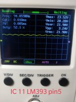
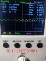
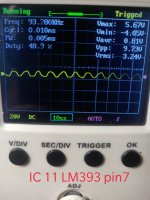
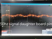
Also have another problem. During all of this checking, I was getting a lot of noise on the signal as seen in the screen shots. Depending on how I moved the board or if it was upside down or right side up it would clean up or get worse until somehow I now have a square wave on pin1 and pin7 of IC6. I still have a clean sine wave on pin5 though and the IC is receiving ±15.5v.
R1 15.5
R2 -15.5
U5
1. 0v
2. 0.2v
3. 1.3v
I assume that the regulated 5v is missing.
Also have another problem. During all of this checking, I was getting a lot of noise on the signal as seen in the screen shots. Depending on how I moved the board or if it was upside down or right side up it would clean up or get worse until somehow I now have a square wave on pin1 and pin7 of IC6. I still have a clean sine wave on pin5 though and the IC is receiving ±15.5v.
- Status
- This old topic is closed. If you want to reopen this topic, contact a moderator using the "Report Post" button.
- Home
- General Interest
- Car Audio
- Kicker KX800.1(40KX8001) powers on but no output