I have a 300/2 here that when powered up displays an increasing power supply duty cycle, by which I mean is starts out more or less like you’d expect but the square waves keep getting wider and wider until it makes a sort of hissing noise. Is this the feedback signal not making its way back to the control IC?
Check the various components between the two CTs on the power transformer. There is also a transistor that drives back to the feedback (pin 1 of the driver board) through one of the diodes.
Pin 2 is generally a reference and should come up quickly as the 3525 receives power. It's generally between 2.5 and 2.8v from my limited notes.
Pin 2 is generally a reference and should come up quickly as the 3525 receives power. It's generally between 2.5 and 2.8v from my limited notes.
Both diodes and the 1-ohm sand resistor check good out of circuit, I followed the trace back from the diodes and it looks like it goes to pin 11 on the driver not pin 1. Output voltage from the power supply is stable at +/-52v, so are the pair of CT’s what it’s using to control duty cycle?
Hope this helps.
For context I took all these measurements as input current was passing through 1.5A (input voltage 13.8), since that’s around the value these typically idle at. If a pin had increasing voltage the longer I kept the remote turned on, it’s noted by an *.
SG3525
1: 0
2: 5.1
3: 350mv*
4: 240mv*
5: 1.6
6: 3.7
7: 1.6
8: 4.9
9: 1.5*
10: 0
11: 2.1*
12: 0
13: 13.1
14: 1.9*
15: 13.1
16: 5.1
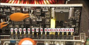
Power supply card
1: 1.5*
2: 2.9
3: 0
4: 80mv
5: .9
6: 0
7: 0
8: 0
9: 11.9
10: 350mv
11: 1.5*
12: 2
13: 13.1
14: 1.5*
15: 5
For context I took all these measurements as input current was passing through 1.5A (input voltage 13.8), since that’s around the value these typically idle at. If a pin had increasing voltage the longer I kept the remote turned on, it’s noted by an *.
SG3525
1: 0
2: 5.1
3: 350mv*
4: 240mv*
5: 1.6
6: 3.7
7: 1.6
8: 4.9
9: 1.5*
10: 0
11: 2.1*
12: 0
13: 13.1
14: 1.9*
15: 13.1
16: 5.1
Power supply card
1: 1.5*
2: 2.9
3: 0
4: 80mv
5: .9
6: 0
7: 0
8: 0
9: 11.9
10: 350mv
11: 1.5*
12: 2
13: 13.1
14: 1.5*
15: 5
- Status
- This old topic is closed. If you want to reopen this topic, contact a moderator using the "Report Post" button.
- Home
- General Interest
- Car Audio
- JL 300/2 excessive power supply duty cycle