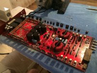
Friend of mine brought an Orion HCCA 25001 a week ago, of course - blowned.
Long story in short, some guy having no real idea of electronics tried to "fix" the amp and made a mess.
Now I have missing parts, some previous replacements that i'm not sure about, some added components...all of the "goodies"
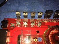
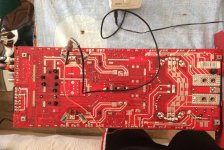
I've cleaned up the amp and brought it back as much as I could to a factory condition. Power supply section seems to be fine. Output section needs a lot of work.
Few question.
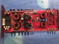
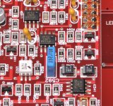
1. At the voltage regulation section there are 3*LM317T and 1*LM337SP at each side of the board. What is the right placement for the LM337SP, because they look rearranged manually ?!
2. In front of each voltage regulator there are 3 SMD resistors - big one 10 ohms, middle 120 ohms and the third is different for almost each regulator and they are all over the place - and yes, i can confirm they have been changed before by the local "tech guy". Where can I find the right values, since I can't find any schematic for this amp ?!
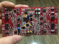
3. There is a small shorted SMD transistor - Q388 right under the driver board, which even with a magnifying glass i can't quite read the markings on it, seems like there is a glue or some kind-a of epoxy on it.
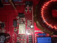
4. At the driver board the marked IC's, are those irs2184s or is it the tl072c + lm211 design ?!
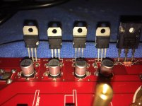
The output mosfets are the original ones - irfp90n20d, 3 of 8 are shorted. I will buy 8 new ones, but i've to fix the voltage regulation section first and see if the driver board has any drive.
There is also something I don't quite understand. There is an ESP BOARD which contains a PIC. Is this PIC used only for troubleshooting and features or it does control the amp, like the PIC's in the brazilian style amplifiers ?
Long story in short, some guy having no real idea of electronics tried to "fix" the amp and made a mess.
Now I have missing parts, some previous replacements that i'm not sure about, some added components...all of the "goodies"
I've cleaned up the amp and brought it back as much as I could to a factory condition. Power supply section seems to be fine. Output section needs a lot of work.
Few question.
1. At the voltage regulation section there are 3*LM317T and 1*LM337SP at each side of the board. What is the right placement for the LM337SP, because they look rearranged manually ?!
2. In front of each voltage regulator there are 3 SMD resistors - big one 10 ohms, middle 120 ohms and the third is different for almost each regulator and they are all over the place - and yes, i can confirm they have been changed before by the local "tech guy". Where can I find the right values, since I can't find any schematic for this amp ?!
3. There is a small shorted SMD transistor - Q388 right under the driver board, which even with a magnifying glass i can't quite read the markings on it, seems like there is a glue or some kind-a of epoxy on it.
4. At the driver board the marked IC's, are those irs2184s or is it the tl072c + lm211 design ?!
The output mosfets are the original ones - irfp90n20d, 3 of 8 are shorted. I will buy 8 new ones, but i've to fix the voltage regulation section first and see if the driver board has any drive.
There is also something I don't quite understand. There is an ESP BOARD which contains a PIC. Is this PIC used only for troubleshooting and features or it does control the amp, like the PIC's in the brazilian style amplifiers ?
Attachments

1. The output leg is different on the 317 and 337. The 10 ohm resistor (that commonly fails) is on the output leg.
2. See attached.
3. No clue
4. See attached.
From what I've seen and from asking around, these amps have a strange anti-clip (?) circuit that makes the output act erratically at clipping. As far as I know, no one has taken the time to resolve this issue and there is no fix.
2. See attached.
3. No clue
4. See attached.
From what I've seen and from asking around, these amps have a strange anti-clip (?) circuit that makes the output act erratically at clipping. As far as I know, no one has taken the time to resolve this issue and there is no fix.
Attachments
Thanks Perry.
1. So the 10ohm resistor is always tied to the output of the voltage regulator, no matter if its the LM317 or LM337 (pin configuration is different indeed)
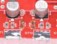
2. Can you post photos of the resistors from the other side of the board near the ICs - 783, 793, 732, 731 ?! They do not match to ICs - 771, 772, 741, 742 ?!
3. Friend of mine has the same amp in working condition. Promised me to take a pic of the transistor.
4. Thank you very much. That's something new to me...never seen before class D with such a drive board.
"makes the output act erratically at clipping." - Do You mean that top sinewave tops out earlier/later that the bottom one ?!
1. So the 10ohm resistor is always tied to the output of the voltage regulator, no matter if its the LM317 or LM337 (pin configuration is different indeed)
2. Can you post photos of the resistors from the other side of the board near the ICs - 783, 793, 732, 731 ?! They do not match to ICs - 771, 772, 741, 742 ?!
3. Friend of mine has the same amp in working condition. Promised me to take a pic of the transistor.
4. Thank you very much. That's something new to me...never seen before class D with such a drive board.
"makes the output act erratically at clipping." - Do You mean that top sinewave tops out earlier/later that the bottom one ?!
1. That's what I've seen in this amp. The 10 ohm resistors were one of the most common problems.
2. I don't have any photos of those resistors. The angle that they were taken from has the caps blocking them.
The top and bottom don't clip at the same point, if I remember correctly. It's not like an offset because that would be consistent. With these amps, the clipping point varies. They may have resolved it but I heard it from others as well so it wasn't just this amp.
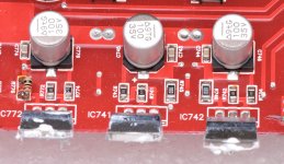
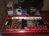
Replaced all the missing parts. Q388 was being replaced with a MMBFJ108, but still i'm not 100% sure that's the right one, but as much as i could read the burnt marking on it, that's it.
Output mosfets are all out. .
PS section works fine. I can even hear the relay in the output section click in.
Didn't know that these amps are working only with positive + rail. There is no any negative - rail.
All of the voltage regulators are getting hot in 5-10 minutes after idling, but that's I guess due to the fact the board is out of the case/heatsink and there is no any cooling surface area attached to them.
I have some suspects that this amp is much more similar to the brazzilian schematic than the ordinary generic class D half bridge Korean ones. It's using even the same output mosfets as the TARAMPS amplifiers - irfp90n20d.
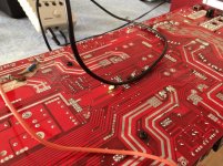
Feeding 35hz sinewave into the RCA - I do have a low gate drive on the 3 of the 4 pads, think it looks OK. The fourth one is kind-a trying to build up but is almost straight DC with tiny bumps. Have to investigate further.
Pictures attached.
Output mosfets are all out. .
PS section works fine. I can even hear the relay in the output section click in.
Didn't know that these amps are working only with positive + rail. There is no any negative - rail.
All of the voltage regulators are getting hot in 5-10 minutes after idling, but that's I guess due to the fact the board is out of the case/heatsink and there is no any cooling surface area attached to them.
I have some suspects that this amp is much more similar to the brazzilian schematic than the ordinary generic class D half bridge Korean ones. It's using even the same output mosfets as the TARAMPS amplifiers - irfp90n20d.
Feeding 35hz sinewave into the RCA - I do have a low gate drive on the 3 of the 4 pads, think it looks OK. The fourth one is kind-a trying to build up but is almost straight DC with tiny bumps. Have to investigate further.
Pictures attached.
Attachments
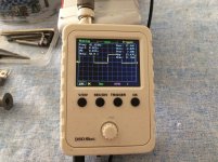
Amplifier has been successfully repaired but still there is an abnormal clipping of the sinewave when the amp is being pushed to its almost full power.
Couldn't fix that, but the customer is happy enough. Says it's sound nice enough for him and he could not hear any distortion.
So i count this one as a "done" one.
Thanks to everybody for the help !
Couldn't fix that, but the customer is happy enough. Says it's sound nice enough for him and he could not hear any distortion.
So i count this one as a "done" one.
Thanks to everybody for the help !
Attachments
- Status
- This old topic is closed. If you want to reopen this topic, contact a moderator using the "Report Post" button.
- Home
- General Interest
- Car Audio
- Orion HCCA 25001 - resurrection issues