Hello diyAudio forum members,
Please let me shortly introduce myself. My name is Max, I'm 25 years old, master student mechanical engineering and interested in audio/amplifier/guitar pedal because of my hobbies.I did some repairs/builds on guitar pedals and guitar wiring and have quite some experience when it comes to soldering. (I'm definatly not an expert, but my skills are adequate.) I'm here to learn from you guys!
Then comes the reason why this is in the class D section. I own a alfa romeo 159 sportwagen with the Bose hifi upgrade. I always noticed that the system lacked bass and recently found out the subwoofer isn't doing anything at all.
So I removed the subwoofer (amplifier + woofer + plastic bass box) and measured the incoming five cables. The first two were regular audio out from the main amplifier, which gave a voltage reading in AC with my dmm. The next signal was a 12V dc which Is used for switching the amp on and off as the voltage dissapears when turning of the head unit in the car. The next two cables were the black mass cable (negative lead) and a regular 12V + cable.
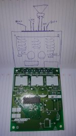
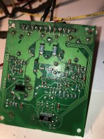
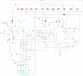
I inspected the bose amplifier and it became clear that it's not that exotic. I removed the 3 inductance coils, some caps and the metal plate in order to trace the pcb. I made a drawing of it in eagle cad, which you guys may know, which can be used in order to create a pcb drawing for manufactering. (I just used it to have a clear drawing of the schematic)
The conclusion came that the VCC in (12V) was detached from the green coil, where the voltage enters the system. As the VCC is twice on the board, I repaired the hole by lightly sanding the coating of the copper pcb plate and soldered a thick cable on it and to the underside of the VCC hole. The amp+subwoofer works now, however, the sound is weak and 'electric' on some notes.
I have a old amplifier at home, can I use it to put a sound signal into the amplifier subwoofer and use my power source with 12V to power the amp and turn it on? This would mean I don't have to put it in my car to test and I can turn it on inside the house. Or is there a better way to inspect the amplifier?
I attached two pictures I found on the internet. I'm currently not at home until this evening (I live in the netherlands) and will post the schematic plus pictures of my actual amplifier when I get home.
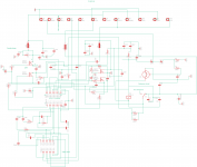
EDIT: note that the schematic is uploaded, but not all names are right, all of the SMD components on the underside are not named. Only the cap's etc on the top. I have not yet identified which mosfet's are on the board, so the name in the schematic is also wrong.
Please let me shortly introduce myself. My name is Max, I'm 25 years old, master student mechanical engineering and interested in audio/amplifier/guitar pedal because of my hobbies.I did some repairs/builds on guitar pedals and guitar wiring and have quite some experience when it comes to soldering. (I'm definatly not an expert, but my skills are adequate.) I'm here to learn from you guys!
Then comes the reason why this is in the class D section. I own a alfa romeo 159 sportwagen with the Bose hifi upgrade. I always noticed that the system lacked bass and recently found out the subwoofer isn't doing anything at all.
So I removed the subwoofer (amplifier + woofer + plastic bass box) and measured the incoming five cables. The first two were regular audio out from the main amplifier, which gave a voltage reading in AC with my dmm. The next signal was a 12V dc which Is used for switching the amp on and off as the voltage dissapears when turning of the head unit in the car. The next two cables were the black mass cable (negative lead) and a regular 12V + cable.
I inspected the bose amplifier and it became clear that it's not that exotic. I removed the 3 inductance coils, some caps and the metal plate in order to trace the pcb. I made a drawing of it in eagle cad, which you guys may know, which can be used in order to create a pcb drawing for manufactering. (I just used it to have a clear drawing of the schematic)
The conclusion came that the VCC in (12V) was detached from the green coil, where the voltage enters the system. As the VCC is twice on the board, I repaired the hole by lightly sanding the coating of the copper pcb plate and soldered a thick cable on it and to the underside of the VCC hole. The amp+subwoofer works now, however, the sound is weak and 'electric' on some notes.
I have a old amplifier at home, can I use it to put a sound signal into the amplifier subwoofer and use my power source with 12V to power the amp and turn it on? This would mean I don't have to put it in my car to test and I can turn it on inside the house. Or is there a better way to inspect the amplifier?
I attached two pictures I found on the internet. I'm currently not at home until this evening (I live in the netherlands) and will post the schematic plus pictures of my actual amplifier when I get home.
EDIT: note that the schematic is uploaded, but not all names are right, all of the SMD components on the underside are not named. Only the cap's etc on the top. I have not yet identified which mosfet's are on the board, so the name in the schematic is also wrong.
Attachments
Last edited:
Yes, I layed the subwoofer assembly in the trunk and reconnected the 5 way connector to the car and simply played a CD. If you want, I can make a movie of it.
What do you think about being able to test it on the bench? I have a power supply which I can put on 12V and a old normal home amplifier.
What do you think about being able to test it on the bench? I have a power supply which I can put on 12V and a old normal home amplifier.
Someone may watch a movie but I won't.
Some of the old versions of the bose amps had balanced inputs so that may be an issue running out of the vehicle.
The description of the sound and not being able to hear it in person (not recorded), may make it difficult to troubleshoot. When something doesn't sound right, the output is generally distorted and to diagnose it, you need to see the output waveform.
I don't have much equipment, I have a DMM, a component tester (which shows caps, resistors, transistors etc) a variable power supply.
I can borrow a oscilloscope from a friend of mine which lives nearby. It doesn't have an output, only inputs. In order to diagnose it, do I need a signal generator?
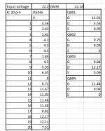
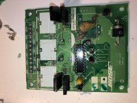
I measured the voltages of the transistors ( and mosfets) and main IC. (the 20 pin one which has a Bose description on top of it) Is it of any use?
I can borrow a oscilloscope from a friend of mine which lives nearby. It doesn't have an output, only inputs. In order to diagnose it, do I need a signal generator?
I measured the voltages of the transistors ( and mosfets) and main IC. (the 20 pin one which has a Bose description on top of it) Is it of any use?
Thank you already for your interest in helping me ") I hope it's okay like this.
I hope it's okay like this.
Here are the voltages. If you need more components or something else, please ask. I also made a audio recording with my phone, but it's made with an iphone so the extension is .m4a, I don't know if you can play that. I think it's from itunes.
It sounds like the recording is bad (like when you record music which is too loud for your recording device), however in reality it sounds almost alike.
I hope it's okay like this.Here are the voltages. If you need more components or something else, please ask. I also made a audio recording with my phone, but it's made with an iphone so the extension is .m4a, I don't know if you can play that. I think it's from itunes.
It sounds like the recording is bad (like when you record music which is too loud for your recording device), however in reality it sounds almost alike.
Attachments
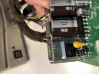
The casing of the transistor says IRF 1 Z 34 G ( If I'm reading it correctly)
Next line on the right is 538P. The GDS are labeled on the pcb.
I'm not sure how they are used, please understand that I have very basic knowledge of amplifier circuits..
For the IC, I found one for sale on ebay with the exact numbering, maybe that will help:
1pcs 134499B Encapsulation DIP-20 | eBay
I once heard something about using some sort of audio probe, going through the circuit that the sound signal goes to find the point where the signal is lost/distorted, is this advisable?
Last edited:
So what would you recommend me to do?
I searched on that part number, I can't make out if it's an I or 1 before the Z. Looking to pictures on the internet the markings look the same, so I think you're definetly right. They are fully insulated.
I already ordered an replacement IC from ebay, is there a way to find out which one it is? Is it possible from the schematic (from my first post) I traced to determine?
I would like to read into class D amplifiers, do you have some sort of source/information that I understand more of how it works?
I'm sorry if I'm asking too many questions...
The ICs could be custom components made only for Bose. If so you will find very little information on them. You could ask on the class D section of this forum to see if anyone recognizes it.
If you want to clean up all of that flux, a toothbrush and acetone (preferred) or alcohol (91%) work well.
Where are the 4 IRFIZ34 FETs?
There is a virtually infinite amount of information on class D amplifiers online. The following are a very basic introduction.
http://www.irf.com/product-info/audio/classdtutorial.pdf
https://www.renesas.com/us/en/www/doc/datasheet/hip4080a.pdf
I will try the acetone with a toothbrush, thanks for the tip, the pcb has definetly seen better days haha.
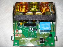
Here are some pictures of the components, I can't seem to get a clear picture of the mosfet. I will try to add some info to the schematic i've drawn in my first post this evening and make it maybe a little more clear to read.
Thanks for the links. As I understood, the signal from the IC is filtered high pass and low pass by the big capacitors and the inductance coils? When you get distorted signals and the filters after the IC seem right, what is the best way to go with diagnosing. I can remove the mosfets and test them with the component tester?
I ordered a xr2206 signal generator kit from china, in combination with the oscilloscope (that i can borrow from a friend) I hope to proper diagnose the amplifier. before and after the bose IC
Attachments
I ordered a cheap signal generator in order to have a simple input on the amplifier, in order to measure distortion with the oscilloscope at the out signal. I don't know if I'm thinking right about it...
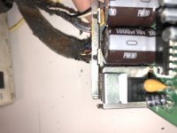
Also, I tested various components. The mosfet's are N-E-Mosfets with values around C = 2.24 uF, Uf = 575 mV and Vt = 3.7V.the four are almost identical in values.
As I understood, the coils and caps work as a high and low pass filter in the class D amplifier. Both coils have values of L = 0.02 mH and a resistance of around 0.1 ohm.
I added a picture of one of the caps (both have the same inscription) and an update scheme to my post. I tested all the traces when I made the schematic, I can't seem to find a faulty component either. Is it possible that the IC itself is blown?
Attachments
Well not to double post, but could you look at this pdf file? It clearly describes the 134499 IC as U2 in older ZR1 corvette bose amps. With the provided schematic (the one I traced from my amp) in the post above, could these be the same?
Luckily, bose used the amp quite often on cars, also a lot of audi's seem to have the amplifier.
Btw, I really appreciate you taking your time to help me!
Luckily, bose used the amp quite often on cars, also a lot of audi's seem to have the amplifier.
Btw, I really appreciate you taking your time to help me!
Attachments
Last edited:
- Status
- This old topic is closed. If you want to reopen this topic, contact a moderator using the "Report Post" button.
- Home
- General Interest
- Car Audio
- Bose car subwoofer amp repair.