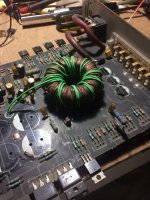
Morning guys, i have this amp to work on the user says they used to have it working on a 24 (yes 24)volt set up, so far i cant see any major mods for it to be a 24volt any major from a 12volt standard supply, my problem is when power up, im only getting 19volts from psu, (even when pull center legs of rectifiers) 19v and about 2 secs youll see it rise to about 23volts.
They are good gate signals they were using 640s with 50n06 in the psu which i removed only leaving the 50s. the volts from the psu is unregulated as when i lower or up the supply input voltage the output voltage will change in significant steps hence why its used on the 24volt supply. When i increase my benchpsu to 15(max) the amp output is at 28 for the rails. i dont know if the transformer was rewound, i just want to know why its not producing an higher voltage for a 12volt amp and 19volts plus and minus is just not sufficient to me for that amp.
They are good gate signals they were using 640s with 50n06 in the psu which i removed only leaving the 50s. the volts from the psu is unregulated as when i lower or up the supply input voltage the output voltage will change in significant steps hence why its used on the 24volt supply. When i increase my benchpsu to 15(max) the amp output is at 28 for the rails. i dont know if the transformer was rewound, i just want to know why its not producing an higher voltage for a 12volt amp and 19volts plus and minus is just not sufficient to me for that amp.
Attachments
Black probe was on that ground plane, readings was with caps, and after, it still the same. Caps are rated at 3300uf my fluke 115 gives me 2838uf for them except a modified extralong one that was place sideways amids the bank (3 genuine, one modified mounted) rated at 4700uf tested at 4528uf.
Most amp (class AB) when i test this way would give me a voltage near 30volts for this type of psu. What is the typical value of the pull down resistors from Grn to B+ in series with 2A472K caps for this amp, im seeing 22ohms? is that correct as im seeing soldering activity around both of them.
Most amp (class AB) when i test this way would give me a voltage near 30volts for this type of psu. What is the typical value of the pull down resistors from Grn to B+ in series with 2A472K caps for this amp, im seeing 22ohms? is that correct as im seeing soldering activity around both of them.
Thats my initial problem Mr Babin, the out put voltage is just not high enough, yes i use the same setting for both and i use the input ground also and its the same readings regardless of centertap ground or amp in ground. The customer says it used to run in a toyota coaster 24volt system, stating it was modified but im just not seeing any unfamiliar modification to restore or what could cause it not to produce sufficient voltage for the rails.
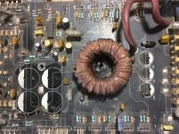
I couldnt say replaced Mr Babin, but i just dont know if the windings were tampered with it seems the legs was soldered (dont know if reinforced or pulled) on the bottom of the amp.
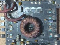
Would it be more secondary windings give more voltage or less? or its a ratio in reference to the primary (like 1:3 or 1:4 somewhat)?
Would it be more secondary windings give more voltage or less? or its a ratio in reference to the primary (like 1:3 or 1:4 somewhat)?
Attachments
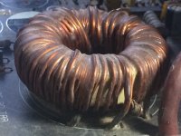
It looks like it may have originally been built for 24v. Desolder the outer secondary windings and add an equal number to both sides. You can do this with whatever small wire you have around to see how many turns you need. When you determine the windings you need for the desired voltage and determine that there is nothing else wrong with the amp, you can wind with the appropriate size wire. Extending the original winding may not be the best option but it shouldn't cause any problems either.
Typically, a car amp transformer will have something like 4+4 on the primary and the secondary windings are used to set the rail voltage (for an unregulated amp). For higher voltages, more primary windings may be needed but it's unlikely that 24 would need more windings. Alternately, you can increase the operating frequency instead of increasing the primary windings if need be to operate at higher voltage. That's not really important when going down in voltage but if you unwound the primary and found 6+6 or 8+8, the higher may be why they used extra primary windings.
For this, I don't think you'll need to unwind the transformer to get the amp working on 12v.
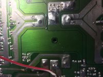
Side note. There are wires across the fuse holder.
Typically, a car amp transformer will have something like 4+4 on the primary and the secondary windings are used to set the rail voltage (for an unregulated amp). For higher voltages, more primary windings may be needed but it's unlikely that 24 would need more windings. Alternately, you can increase the operating frequency instead of increasing the primary windings if need be to operate at higher voltage. That's not really important when going down in voltage but if you unwound the primary and found 6+6 or 8+8, the higher may be why they used extra primary windings.
For this, I don't think you'll need to unwind the transformer to get the amp working on 12v.
Side note. There are wires across the fuse holder.
Last edited:
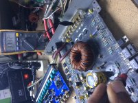
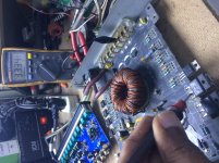
Ive added 10 turns (joined) to the transformer and the voltage is up to 29.7v +/- on the rectifiers as you suggested, is that a suitable voltage to run the amp or as you also stated that 55volts (27.5v+/-) would be what you are expecting from the psu?
Will there be an overshot after replacing the rail caps, or if an overshoot, what would be the warning signs to look for (increased opamp voltage) i think the output have an higher tolerance exceeding 60volts likewise the drivers.
Thanks for the side note, i didnt have any fuse in the amp so i use one strand of wire across.
Attachments
The voltage I mentioned was to get back to the 4 ohm power the amp should have. I should have used a calculator.
It's supposed to produce 150w into 4 ohms.
P=E^2/R
E^2 =PR=150*4
E^2=600
E=24.5
That's RMS voltage. Multiply *1.4 to get peak voltage and the DC voltage per rail. ±34v for 150w into 4 ohms.
As long as you have some capacitance on the rails, what you have now should be close to what you will have with the new caps. When you load it, the rails will drop some due to a lack of regulation.
What are the outputs? TIP35/36 can take ±50v (max).
The regulators will determine the op-amp supply voltage.
Hold the alt key down, type 0177 and release the alt key.
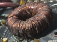
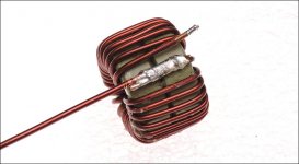
I'd extend it with about a 12g wire (or whatever the original secondary wire is). Strip about 1/2" of enamel back on both and desolder as much as possible. Bind the two wires together with a smaller (20g?) wire so they are tight together then solder them together. The connection point shouldn't be too tight against the other windings because it will be more likely to bite into them, even through heatshrink, unless you make it thick. Attached is a similar repair where braid was used.
I'd extend it with about a 12g wire (or whatever the original secondary wire is). Strip about 1/2" of enamel back on both and desolder as much as possible. Bind the two wires together with a smaller (20g?) wire so they are tight together then solder them together. The connection point shouldn't be too tight against the other windings because it will be more likely to bite into them, even through heatshrink, unless you make it thick. Attached is a similar repair where braid was used.
Attachments
Ive manage to get the magnet wire from a speaker friend (he also does transformer rewinding). Ive add the 10 turns and im up to ±33.34v, ive played it and its ok, just a slight higher gain on one of the channels as the functions switch and gain and crossover levels are stuck due to water contaminations. ive sprayed WD40 and they are just stuck and i fear if i try to apply more force the stems will wring out/off.
as i said its just slight, he is ok with it as the gain is up and he has it on a channel separating crossover and its stuck in the full pass setting.
I'll just add the new caps and mount it when all is done.
as i said its just slight, he is ok with it as the gain is up and he has it on a channel separating crossover and its stuck in the full pass setting.
I'll just add the new caps and mount it when all is done.
Attachments
- Status
- This old topic is closed. If you want to reopen this topic, contact a moderator using the "Report Post" button.
- Home
- General Interest
- Car Audio
- Hifonics Son of Boltar PSU Probs