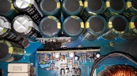
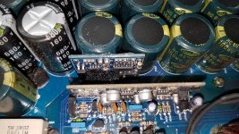
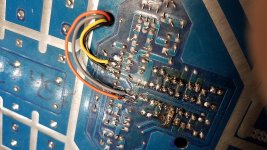
The amp is a crossfire xs4k. it is a board added by another repair shop. Attached is a picture of the board removed. The amp uses a tl494 sister board as with most korean amps. Traces were cut and this was added.
Attachments
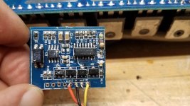
SG3525 LM358 Driver Board. See:
Amazon.com: Bettal DC 12V-24V SG3525 LM358 Inverter Mixer Preamp Driver Board Frequency Adjustable: Home Audio & Theater
Amazon.com: Bettal DC 12V-24V SG3525 LM358 Inverter Mixer Preamp Driver Board Frequency Adjustable: Home Audio & Theater
No Perry there isnt. I contacted the tech that installed the secondary board.
He stated that the tl494 has a flaw that will cause the amp to blow when power is removed and re-applied again so he installed this board to keep that from happening. Well first thing is the amp blew when his customer installed it.
I'm not bashing the tech just relaying the events. i had never seen or heard of anyone doing this mod. and got the information just this afternoon. I am just going to restore it to factory or as close to factory as i can.
Attachments
I've seen bad designs cause the types of failures that you described. It's typically due to the soft-start circuit, using pin 4 of the 494. You can often see it in the current draw as or just after the remote is removed. There will be a spike in current where there should be no current draw. I don't know if this applies to this amp.
It depends.
In some amps, the SS can be eliminated by removing the electrolytic cap between the 5V output and pin 4, then connecting pin 4 directly to pin 7.
In some amps, deadtime is programmed into the drive circuit via a voltage divider. For those amps, pin 4 cannot be grounded.
Modification should not be done without thorough testing because it could make things worse.
Well just to be safe i will just put a new card in from the factory. In case there has been any unwanted tampering. I powered it up and the sign wave looks good but the traces have been cut that go to the drive transistors so there was no load on the card. The new card will be here tomorrow. I love crossfire they get me the stuff i need promptly.
View attachment 719805
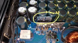
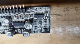
I have also come upon a real head scratcher. Q4 in the picture is removed. but is the same as Q6 on another card with the same model number and revision. BR is the smd code but I find several parts listed and no reference on mouser for the sot23 package. Do you have the parts number would be great for future reference.
Attachments
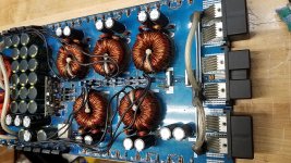
OK. I received power supply driver card and installed it. Replaced all gate resistors. Powered the amp, checked the drive wave on all gate pads and all looked good. I then removed audio driver card for my own personal reasons, due to the amp has been repair shadily. Then installed one pair of 3205's per transformer, reapplied power setting my power supply for 5 amp current limiting. After 30 seconds or so, one pair of the FETS failed along with their drive transistors. I removed those FETS and drive transistors, reapplied power and another pair of FETS and drive transistors failed again. Any ideas as to why with no load other than the amp section with no drive card?
No sir. But should be able to power up without heat sink without a load for a while. Even with a small load. But I think I have found the issue. In this circuit, the gate resistors that were present when i got the amp in for repair were in fact 47ohm. That is incorrect. They should be 22 ohm after contacting the manufacture. Your thoughts?
It could be several things. The 47 ohm with 3205s is OK unless there is another problem. It could be the pulldown resistors (was a problem in a lot of amps) or other drive circuit issues. This one appears to be one of the amps that use the 510 ohm resistor in series between the driver IC and the driver transistors. I've heard of that causing problems in some amps.
I had some MTX amps that would make the FETs run hot, no matter what I did (changed frequncy, driver transistors, gate resistors, driver IC...) No matter what, the FETs would overheat. Even when clamped, they would run hot at idle. That doesn't apply here but it's amazing what you can find when doing repair work.
I had some MTX amps that would make the FETs run hot, no matter what I did (changed frequncy, driver transistors, gate resistors, driver IC...) No matter what, the FETs would overheat. Even when clamped, they would run hot at idle. That doesn't apply here but it's amazing what you can find when doing repair work.
- Status
- This old topic is closed. If you want to reopen this topic, contact a moderator using the "Report Post" button.
- Home
- General Interest
- Car Audio
- Has anyone seen this before?