A request at the manufacturer itself "Audio Control" don't provide the wanted information. Only the owner's manuals was available as pdf-file (see attachment). Who can upload for me the schematics or at least the detailled wiring diagram to the detector control device, that is a set-up consist of a stereo potentiometer 2x10kB and a six pole push-pull switch ?
Thank you very much.
Thank you very much.
Attachments
Now I have find out additional informations.
1) EPICENTER:
based on the patent
Patent US4698842 - Audio processing system for restoring bass frequencies - Google Patents
PCB-numbering:
a) mainboard 080034B (version from the year 1989) and
b) dash control unit PCB 080033
In use are follow operational amplifiers: 6 pcs XR4136 (RC4136) and 1 pcs BA4560.
Additional there are a dual rs flip flop HEF4013 and a VCA (OTA) LM13600. The internal power supply is a SMPS, which creates from a single voltage (12-14VDC) a dual voltage (I guess approx. +/- 7-12VDC).
Three of at whole four wires to the dash control comes from the supply ("+"/"-"/GND) and one wire comes from PIN 1 of the LM13600 (accross a 43 K resistor).
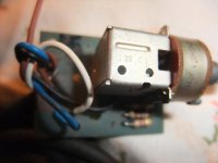
The question for me is now, how must I connect the dash control with this four wires. The dash control consist of a stereo potentiometer (2x10KB) a LED, a dual switch (2 x ON) and three resistors: 2K2 for the LED, 470 ohms and 10 K.
2) ESP-2
PCB numbering
a) mainboard 080047
b) dash control unit PCB: 080048
In use are follow operational amplifiers: 6 pcs BA4560N (SIP) and 1 pcs dbx2150 - go to
http://www.thatcorp.com/2180-series_Pre-Trimmed_Blackmer_IC_Voltage-Controlled_Amplifiers.shtml
The internal power supply is also a SMPS, which creates from a single voltage (12-14VDC) a dual voltage (I guess approx. +/- 7-12VDC). Here isn't realize a discrete solution as to find in EPICENTER. The oscillator was realized with the SG3524 - go to
http://www.ti.com/product/sg3524
Three of at whole four wires to the dash control comes from the supply ("+"/"-"/GND) and one wire comes from PIN 3 of the dbx2150 (accross a emitter follower with 2N4401 and a voltage divider 5K6/15R).
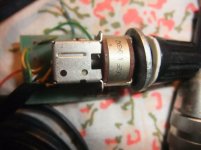
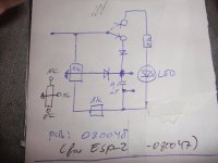
The question for me is basically the same as above; how must I connect the dash control with this four wires. The dash control consist again of a stereo potentiometer (2x10KB) a LED but in opposite to above mentioned version for EPICENTER only a single switch (toggle) and two 1K resistors additional one 100nF capacitor and two diodes 1N4007.
It would be an easy task for me, if I had a detailled circuit diagram on my table.
1) EPICENTER:
based on the patent
Patent US4698842 - Audio processing system for restoring bass frequencies - Google Patents
PCB-numbering:
a) mainboard 080034B (version from the year 1989) and
b) dash control unit PCB 080033
In use are follow operational amplifiers: 6 pcs XR4136 (RC4136) and 1 pcs BA4560.
Additional there are a dual rs flip flop HEF4013 and a VCA (OTA) LM13600. The internal power supply is a SMPS, which creates from a single voltage (12-14VDC) a dual voltage (I guess approx. +/- 7-12VDC).
Three of at whole four wires to the dash control comes from the supply ("+"/"-"/GND) and one wire comes from PIN 1 of the LM13600 (accross a 43 K resistor).
The question for me is now, how must I connect the dash control with this four wires. The dash control consist of a stereo potentiometer (2x10KB) a LED, a dual switch (2 x ON) and three resistors: 2K2 for the LED, 470 ohms and 10 K.
2) ESP-2
PCB numbering
a) mainboard 080047
b) dash control unit PCB: 080048
In use are follow operational amplifiers: 6 pcs BA4560N (SIP) and 1 pcs dbx2150 - go to
http://www.thatcorp.com/2180-series_Pre-Trimmed_Blackmer_IC_Voltage-Controlled_Amplifiers.shtml
The internal power supply is also a SMPS, which creates from a single voltage (12-14VDC) a dual voltage (I guess approx. +/- 7-12VDC). Here isn't realize a discrete solution as to find in EPICENTER. The oscillator was realized with the SG3524 - go to
http://www.ti.com/product/sg3524
Three of at whole four wires to the dash control comes from the supply ("+"/"-"/GND) and one wire comes from PIN 3 of the dbx2150 (accross a emitter follower with 2N4401 and a voltage divider 5K6/15R).
The question for me is basically the same as above; how must I connect the dash control with this four wires. The dash control consist again of a stereo potentiometer (2x10KB) a LED but in opposite to above mentioned version for EPICENTER only a single switch (toggle) and two 1K resistors additional one 100nF capacitor and two diodes 1N4007.
It would be an easy task for me, if I had a detailled circuit diagram on my table.
Last edited:
")
Maybe a repair resp. troubleshooting is necessary, but first step must be to find out the detailled wiring diagram between the mainboard and the Dashboard Restoration Control’s remote device (see my previous posting) for a function test resp. operation test. Sorry for my bad english.
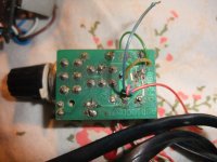
By upload the image - each from the mainboards and both Restoration Control’s remote devices, where is clearly to see the colors and places of the mentioned four connector-cables, I must be able to find out this without schematic diagram from the manufacturer. Who can do this for me?
Thank you in advance. But note the mentioned PCB numbers in the previous posting - there are a lot of other versions from the mentioned models.
Last edited:
In the attachment the associated images and schemas for both dash control units. Who can create the correct wiring diagram with help of the mentioned informations and the schemas?
Attachments
-
 Audio Control PCB Component Side 080033 for EPICENTER 080034B.jpg851.6 KB · Views: 468
 -
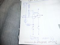 Audio Control Schema 080033 for EPICENTER 080034B.jpg829.3 KB · Views: 459
 -
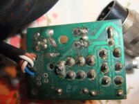 Audio Control PCB Solder Side 080033 for EPICENTER 080034B.jpg999.9 KB · Views: 609
 -
 Audio Control PCB Component Side 080048 for ESP2 080047.jpg978.6 KB · Views: 550
 -
 Audio Control Schema 080048 for ESP-2 080047.jpg868.7 KB · Views: 799
 -
 Audio Control PCB Solder Side 080048 for ESP2 080047.jpg961.8 KB · Views: 694
Last edited:
What happened to the 4C telephone cable that was used to connect the two devices? The connection would be stone simple and you wouldn't need schematics to figure this out.
I used to do warranty work on these, but all that info was left with the shop when I sold it. I don't know if I have anything floating around for them here.
-Chris
I used to do warranty work on these, but all that info was left with the shop when I sold it. I don't know if I have anything floating around for them here.
-Chris
- Status
- This old topic is closed. If you want to reopen this topic, contact a moderator using the "Report Post" button.
- Home
- General Interest
- Car Audio
- Audio Control "ESP-2"/"The Epicenter" - Schematic wanted