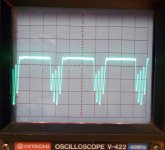
Had a JL Audio 500/5 for repair with a noise signal on the sub-channel but only when the RCA cables were plugged in but no noise signal without. See Pictures. Scope is set to 10V per division, timebase 5ms per division. Signal goes positive for about +5VDC then negative to about -30VDC.
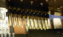
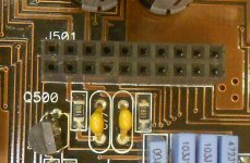
Problem found to be a burned pin on the top board on P501, 4th pin in from the left bottom row. Should be connected to ground through socket J501 on bottom board. But a open ground connection could just have been as easily caused by bad solder connection on the connector or a loose pin connection so I mention it here.
If you see this noise signal signal symtom on the sub channel of your JL 500/5 you might want to check this pin connection.
Attachments
You should note the coupling mode when giving the scope settings. The scope had to be set to AC coupling here.
The audio output on the sub channel is biased to +35v (approximately) on both the positive and negative speaker terminals. There is no negative voltage.
The waveform was taken accross the speakers terminals, not from amp power ground so even though it was set to DC coupling it would not make a difference in the viewed waveform- AC or DC coupled. The ground was set to the center line. I only mentioned the voltages for visual purposes.
You should have mentioned that you were using the scope in differential mode or with a differential probe. Virtually no one does that.
All I'm trying to do is clarify what has been posted. Without specific information about the scope settings, it makes it difficult to understand what the scope is showing.
All I'm trying to do is clarify what has been posted. Without specific information about the scope settings, it makes it difficult to understand what the scope is showing.
You should have mentioned that you were using the scope in differential mode or with a differential probe. Virtually no one does that.
All I'm trying to do is clarify what has been posted. Without specific information about the scope settings, it makes it difficult to understand what the scope is showing.
No differential probe or differential mode was used. Standard scope probe measuring accross the sub-channel speaker terminals.
That's dangerous for most scopes. The shield ground on the probe is connected to the case of the scope which is connected to the mains ground via the ground prong on the AC power plug.
Most DC power supplies also have a ground that's connected to a mains ground.
If you do this with a scope and DC power supply that have 3-prong mains plugs, you risk damaging the scope.
If you do this with a scope without a good ground between the case and the mains ground, this will put DC voltage on the case of the scope. At 35v, it's not a significant danger. If this is done with higher voltage (rail voltage on a larger amp could be 150v+), it could be a real danger to anyone who touches the scope when it's connected to the amp.
That's dangerous for most scopes. The shield ground on the probe is connected to the case of the scope which is connected to the mains ground via the ground prong on the AC power plug.
Most DC power supplies also have a ground that's connected to a mains ground.
If you do this with a scope and DC power supply that have 3-prong mains plugs, you risk damaging the scope.
If you do this with a scope without a good ground between the case and the mains ground, this will put DC voltage on the case of the scope. At 35v, it's not a significant danger. If this is done with higher voltage (rail voltage on a larger amp could be 150v+), it could be a real danger to anyone who touches the scope when it's connected to the amp.
I used a adapter on my scope so the ground pin on the plug is not connected, did not use my DC power supply but a battery during this test but do I understand what your saying.
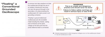
Those reading this should understand that floating a scope ground can result in electrocution.
If someone needs to read across two points that have voltage on them, a differential probe or a differential setup (using two probes and both scope channels) should be used.
It should be clarified that is only the case if you have the ground lead on a voltage point will the case of the scope have voltage on it. Every place I've have worked at use the adapters on the scopes. And for very good reason.
In a lot of equipment measurements must be made on a board close to high voltage sources. If your scope ground lead is grounded and comes off and touches a 480VAC line you can and will be badly burned by a arc flash not to mention your scope seriously damaged. Same situation if you connect to a high voltage point you assume is ground or common but is not. A lot of field techs have portable scopes so they have no worries but where the equipment is built and tested older bench scopes are used and so adapters must be used.
If your scope is isolated from ground and you have a standard scope and the ground lead touches 480v and someone is leaning against the case of the scope, you likely have a dead co-worker. The company that employs such techs would be better off spending a few hundred $ on a differential probe than setting themselves up for a lawsuit.
If you're going to use dangerous practices, you need to state what the dangers are so that newbies don't end up injured or dead.
I've never seen anywhere that this was acceptable. The following document has the warnings for floating grounds on conventional scopes (attached screen caps).
http://www.newark.com/pdfs/techarticles/tektronix/FFM.pdf
Attachments
If your scope is isolated from ground and you have a standard scope and the ground lead touches 480v and someone is leaning against the case of the scope, you likely have a dead co-worker. The company that employs such techs would be better off spending a few hundred $ on a differential probe than setting themselves up for a lawsuit.
If you're going to use dangerous practices, you need to state what the dangers are so that newbies don't end up injured or dead.
I've never seen anywhere that this was acceptable. The following document has the warnings for floating grounds on conventional scopes (attached screen caps).
http://www.newark.com/pdfs/techarticles/tektronix/FFM.pdf
Equipment supplied by 480 three phase (delta config) voltage is not grounded thru it's voltage source but must be grounded with a separate line. In the example above it does not look like the equipment (UUT) is grounded which is a much much more serious safety issue.
For someone to get a shock 2 unlikely things have to happen.
A. Someone has to intentionally or accidently clip the ground clip on a voltage source and not ground and leave it there not realizing thier mistake for some significant amount of time.
B That same person or someone else has to then reach and touch a unpainted metal part of the scope. If its a DC voltage it will have to be close to a 100 volts or more to even feel it.
If that same person had the lead grounded and did the same thing touching a high voltage source most likely would have burnt fingers, damaged equipment or board, damaged scope, circuit breaker or fuse blow on mains. I've seen it happen several times during my work but have never seen anyone get shocked by using a floating scope ground.
What you say is true but in reality if the equipment you are working on is grounded it does not make you safer and risks burns and damaged equipment.
Last edited:
This is unsafe.
If you need to read across two live points, use differential input.
If you're worried about the ground lead, insert a high-voltage, low-current fuse in it.
I'm done with this. If someone tries what you're suggesting and is injured or killed, I hope you have good lawyers. I'm not doing this because I have a desire to argue about it. This is dangerous.
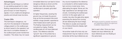
JL Audio Sub-Channel Waveform Referenced From Ground.
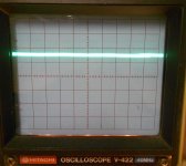
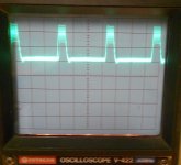
This is the noise on JL Audio 500/5 sub-channel as referenced from the amp power ground. Scope settings are- DC coupled, timebase 5ms, voltage 20V per division, ground reference set on centerline.
The first picture is of the sub-channel no input or RCA cables connected, same voltage (+) & (-) terminals.
The second picture is with the RCA cables connected, no signal (-) terminal.
The third picture is with the RCA cables connected, no signal (+) terminal.
Attachments
- Status
- This old topic is closed. If you want to reopen this topic, contact a moderator using the "Report Post" button.
- Home
- General Interest
- Car Audio
- JL Audio 500/5 Noise and Distortion on Sub-Channel Troubleshooting Tip.