I have a JL 500/1 Rev3 amplifier that when powered the green light comes on but has absolutly no audio output. I measured the speaker terminals and no juice there. I have a sine/square wave generator as my signal and am using a 100hz sinewave signal at 3v.
From Perry- "I need the DC voltage on all 10 pins of the 10 pin connector on the preamp board. Use the pin numbering shown on the JL500 page."
Here you go.
w/signal sensing off --- ----- w/signal sensing on (but remote wire still being used)
1) 0.001
2) 0.001
3) 12.74
4) 0.001 -------- ----- 0.014
5) 0.001
6) 0.001
7) 0.001
8) 0.001
9) 0.001 -------- ----- - 0.005
10) 0.001
Most of the pins that read 0.001 where reading back and foward 0.000 to 0.001. Pin 4 and 9 are the only ones that barely change when I switch the signal sensing on. Although I've read on the owners manual that the signal sensing only works with hi-speaker output signals and has to be midrange frequency. Which am using 100hz (low frequency) so I havent had the amplifier cut on with "Signal Sensing" switch, I have to use the remote wire.
This may be good news or bad news. But I keep recheking the board closer and closer to see why nothing is burnt and why I have no power on the pins. Well I found R627 broken off of the board (not burnt or blown) just not on the board, but the pins where left behind.
Does anyone have the value of R627, I dont know what this resistors does but it look slike it goes to the smaller two transformers (toroid, smaller doughnuts lol) and power those up. Hopefully its not a bad sign of something worse.
Can't wait for Perry's thoughts, he has helped me before fixed my other amplifiers. Thanks to him and his tutorial (worth every penny and full of good info).
It may have popped or exploded off the board but no heavy signs of black residue left behind. I actually thought it was normal until I saw "R627" by it and checked Perry's pics and saw an SMT resistor on R627 but on his pic I can't tell value.
Last edited:
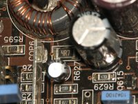
What is the size and watt rating (am pretty its 1% tolerance, am assuming 1/2watt??), am kinda new to SMT (notice how they had different resistors for SMT just like through hole). Also what is the purpose of that resistor, to me it looks like its just to let power to the transformers and pretty much all the IC chips.
And if possible what would cause this resistor to blow up (it was on the board half on each pad cracked right down the middle) at first when I saw it I though it was normal and where pins for something below the board, thats until I saw Perry's pics.
And if possible what would cause this resistor to blow up (it was on the board half on each pad cracked right down the middle) at first when I saw it I though it was normal and where pins for something below the board, thats until I saw Perry's pics.
Last edited:
Okay I got some from Mouser (about 12miles away from me). I have the amplifier with the bottom up and I solder the new resistor and tested it. It turned on and produce audio but I barely touched the amplifier causing it to barely move and the resistor popped.
I installed another one and this time I didnt touch the amplifier and made sure it didnt move and it stayed one for a while (20minutes without getting hot on a 32hz sine wave signal).
So I turned the amplifier off and turned it right side up (LEDs showing) and the amplifier DID NOT produce any sound and when I checked again the board, it popped AGAIN the same resistor.
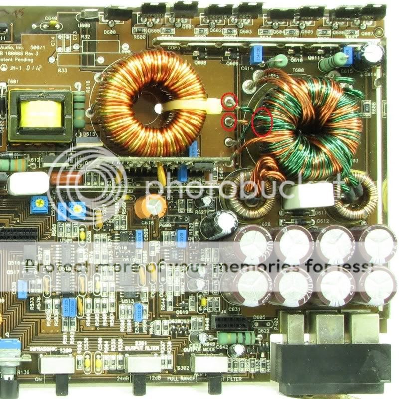
Looking closer to the big transformer it looks like it may have a short on the bottom where the lead are bent and in the board.
Does anyone know if the transformer is causing this and what to use. I circle in red on the picture to show which leads am reffering to and where the short might be, its below the doughnut (transformer).
I installed another one and this time I didnt touch the amplifier and made sure it didnt move and it stayed one for a while (20minutes without getting hot on a 32hz sine wave signal).
So I turned the amplifier off and turned it right side up (LEDs showing) and the amplifier DID NOT produce any sound and when I checked again the board, it popped AGAIN the same resistor.
Looking closer to the big transformer it looks like it may have a short on the bottom where the lead are bent and in the board.
Does anyone know if the transformer is causing this and what to use. I circle in red on the picture to show which leads am reffering to and where the short might be, its below the doughnut (transformer).
Last edited:
Okay it wasnt the transformer. I found out that the ground terminal was kinda off set from the power (more lower than the power terminal). So I took it apart and notice right away that the ground was almost off the board and touching (making contact) with the pre-amp board. I guess thats why it kept popping the 4.7ohm resistor. I desolder it and fixed it and added some extra protection to make sure the terminals didnt make contact with the pre-amp board again.
Tested it with a sine wave of 32hz and speakers terminals where producing 20v (when adjusting the gain) it calls for 44.7v @ 4ohm load but I adjusted it to 20v due to no enclosure. I left it on and playing the sine wave for 1hr straight and it barely got warm, I guess its because it was kinda cold in the garage.
Thanks to Perry's tutorial, I was able to find out the problem.
- Status
- This old topic is closed. If you want to reopen this topic, contact a moderator using the "Report Post" button.