Just started building audiosector lm3875 standard kit.
I'm reusing a transformer, which I've measured at 25 volts on secondaries
However, the DC output after the rectifier is +49V on V+ and PG+, and -54V on V- and PG- !
This was a lot more than I was expecting! I would've thought 25 * 1.41 = 35V DC ?
I've checked soldering and connections and can't spot anything wrong, does anyone have any ideas?
Cheers,
geoff.
measure the open circuit output voltages. Measure (safely) the input voltage.
That will give you enough information to work out the maximum AC voltage when mains is at 253Vac, the maximum on a UK supply.
Using a 230:25Vac 7% regulation transformer expect the maximum output voltage to be
Vout = Vin/Vrated * Voutrated * (1+regulation)
Vin = 240 nominal
Voutrated =25
Vout = 240/230*25*(1+0.07) = 27.9Vac
Max Vout = 253/230*25*1.07 = 29.4Vac
Max DC is 29.4*sqrt(2) -0.5Vf ~41.1Vdc
250VAC mains
Thanks Andrew, I did not realize the mains voltage went that high, but just measured it at ~250vac. secondaries are just over ~25vac, and dc voltage after the rectifier is ~50vdc
I assume something is wrong with the rectifier, just not sure how to diagnose it further. All the diodes seem to be ok according to my dmm.
Thanks,
geoff.
±24Vdc from a 25-0-25Vac transformer is still not right.I had originally connected PG+ and PG- DC output grounds to common / star ground. If I remove this, I get +- 24vdc output.
geoff.
Post info as requested by JMF.
Did you use the Mains Bulb Tester?
Is the bulb lit bright, or glowing?
Diagrams
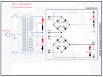
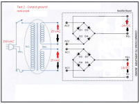
Ok, excuse the sloppy ms paint work, attached is the original diagram from the kit, and the two tests I have performed, the first with ground connected getting ~+- 50VDC, the second with ground removed at around +-25VDC
I did use a mains bulb tester, but did not see the bulb light up at all.
Cheers,
geoff.
Attachments
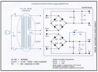
The middle diagram shows 250Vac input and 25Vac output.
This seems impossible for a 230:25Vac transformer !
As stated in post2, expect ~29Vac from a 230:25Vac 7% regulation transformer connected to 250Vac
This seems impossible for a 230:25Vac transformer !
As stated in post2, expect ~29Vac from a 230:25Vac 7% regulation transformer connected to 250Vac
Max Vout = 253/230*25*1.07 = 29.4Vac
Not sure exactly what the transformer is rated at, as I'm reusing an old b&o amplifier chassis and transformer. The 25VAC is what I measured on the secondaries using a multimeter.
The service manual is still online here:
http://www.vintageshifi.com/reperto...Bang-Olufsen-MCL_Converter-Service-manual.pdf
They seem to be showing 33VDC after rectification.
Cheers,
geoff.
The service manual is still online here:
http://www.vintageshifi.com/reperto...Bang-Olufsen-MCL_Converter-Service-manual.pdf
They seem to be showing 33VDC after rectification.
Cheers,
geoff.
You are not measuring DC when attaching probes to the rectifier. You are measuring the average voltage of the rectified sinewave.
You need to add the smoothing capacitor to be able to store the DC voltage and then attach your probes.
Thanks Andrew, that makes sense! For some reason the kit doesn't include the smoothing capacitors. This was mentioned in the manual:
Code:
If we measure approx. +/- 20V (positive will be lower because of LED) we are ready to connect amp boards.
Please note that voltages are much lower than expected beacuse of lack of smoothing caps.
If you have 10uF caps installed on rectifiers board both voltages would exceed 30V DC
Thanks for all your help on this, much appreciated!
geoff.
Correct that to: "after rectification and smoothing"They seem to be showing 33VDC after rectification.
You are missing C1 and C2 filter caps, which will charge to peak value of 25V minus diode loss, so some:
(25*1.4142)- 1.4 .
Do the Math yourself
")
Hi Mark,
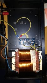
There used to be a connection via a 220k resistor from the secondary the ground, but removing this seemed to make no difference to the DC voltages after the rectifier.
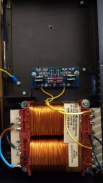
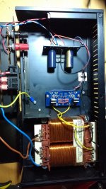
Attached is a photo with the grounds still attached.
The schematic (on page 14-5) shows connections between 10->14 and 11->16 on the transformer. You have connected 10 to one PSU input and 14 to the other input. Best to check that the secondaries are not connected as shown in the schematic.
Ordered some smoothing capacitors, as I do not have any of the right voltage.
If I connect 10->14, I think that would essentially make it more like a centre tapped transformer? In which case, should I be removing the diodes as per this post:
http://www.diyaudio.com/forums/chip...oid-wiring-peter-daniels-kit.html#post1196283
Cheers,
geoff.
If I connect 10->14, I think that would essentially make it more like a centre tapped transformer? In which case, should I be removing the diodes as per this post:
http://www.diyaudio.com/forums/chip...oid-wiring-peter-daniels-kit.html#post1196283
Cheers,
geoff.
Yes.
Retain 4 diodes to mimic the bridge rectifier.
You must not connect a dual bridge rectifier to a centre tapped transformer.
Use a Mains Bulb Tester to power ON every restart until after you have completed your last modification. It will prevent you blowing up your project if you make a wiring mistake.
Ok, re-wired the bridge to use 4 diodes, now I get the following voltages
V+ to V- 46 volts
V+ to ground(black wire from transfomer) 23 volts
V- to ground(black wire from transfomer) -23 volts
Which I think is expected without the smoothing capacitors in place.
Cheers,
geoff.
V+ to V- 46 volts
V+ to ground(black wire from transfomer) 23 volts
V- to ground(black wire from transfomer) -23 volts
Which I think is expected without the smoothing capacitors in place.
Cheers,
geoff.
Attachments
- Status
- This old topic is closed. If you want to reopen this topic, contact a moderator using the "Report Post" button.
- Home
- More Vendors...
- Audio Sector
- LM3875 Kit, too much voltage