I'd like to present here a power supply board that can be used in many different ways. It's been offered for quite some time now with various amp group buys, but the application info has never been consistently gathered in one place.
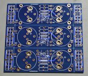
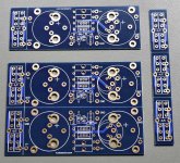
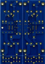
The most recent version consists of 6 small rectifier boards and 3 main supply boards (two positive, one negative), all separated with scoring lines.
A complete board is available at $30, however, normally I separate it into smaller sections. So, I first remove rectifier strip on the right and then, depending on requirement, I either remove top positive supply board, or lower negative supply board.
In this way, I'm having either a symmetrical amp PS pcb (good for F4, F5, AJ-X amps) or dual positive supply (F2, F3). The remaining positive board can be used to supply small power line stages (like Shigaclone), more on that later.
Dual supply boards are avaialble at $20, single supplies at $10. Small rectifier boards are avaialble free of charge, either added to amp board order or separately.
Attachments
Last edited:
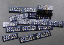
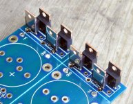
The rectifier section accepts high power diodes mounted as in a picture below (they can be attached directly to a chassis for heat dissipation, isolation pads needed). The board is designed mainly for 3 pin rectifiers, but will work with other diodes packages as well. Here's MUR3060:
Attachments
The two pin rectifiers will work too, however, because one of the pins is hanging not connected now, you need to use jumpers between center pad and outer pin. The jumpers install like in a picture below (opposite the white stripes which mark something else). You can also bend the pins and use them as jumpers.
Attachments
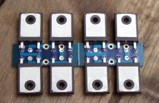
The white stripes mark the spots to install rectifiers in TO-220 packages (like MUR860).
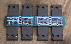
Picture below also shows how rectifier board connects to the PS board: use 4 wires for DC, wires from transformer secondaries connect to pads marked A/C (one secondary to one set of diodes, the other to a second set).
In case of TO-220 diodes, their pins can be used as jumpers to connect directly with traces to capacitors.
Attachments
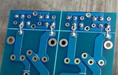
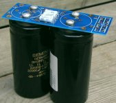
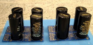
For power amp application, we are only interested with two large caps and 4 resistors (usually 0.47R), the additional small components are not being used here; those are reserved for small power regulators in supplying line stages.
The board will accept up to 50mm capacitors, including caps with screw terminals like those Sikorels below.
The board will accept up to 50mm capacitors, including caps with screw terminals like those Sikorels below.
Attachments
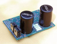
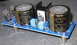
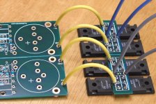
Attached picture shows it for LM317 (top) and LM337 (bottom), the orientation and placement of TO-220 regulators is critical as the supply boards work with symetrical voltages.
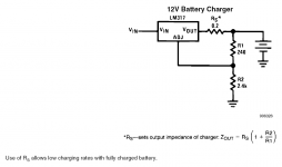
The other parts values are according to schematic in a picture:
R1/R3 = 120R
R2/R4: adjustable 2K, can be later replaced with a fixed value
C1-C4 = 0.1uF (optional, any other small value should work fine too))
C5/C6 = 10uF
Choose any suitable values for large caps. Although grounds are shown as common in a schematic (courtesy of National Semi), they are kept separately on my boards.
That arrangement is also good for LT1086/LT1033.
The other two spots are reserved for LM78xx/LM79xx
Attachments
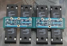
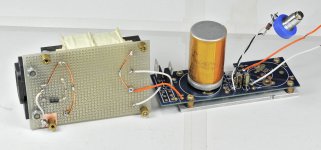
Here's a charger (based on LM317) for battery supply with my Fertin drivers. The output cap is BG N 10/50, small caps not used.
Also, powering CD Player.
Also, powering CD Player.
Attachments
Last edited:
Jensens would probably be the top grade option, although a bit expensive.
Nichicons KG Super Through would be my next choice.
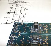
For other board options, use regulators datasheet and use recommended components. Here's one such schematic from LM317 datasheet.
Nichicons KG Super Through would be my next choice.
For other board options, use regulators datasheet and use recommended components. Here's one such schematic from LM317 datasheet.
Attachments
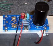
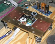
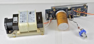
I'd like to present here an example how to implement those boards in a stand alone PS.
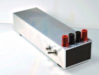
I like to use 2 x 3 aluminum tubing for all my projects now. It simplifies chassis building as the main body of an enclosure consist of a single tube section cut to the required size, the end panels are really optional.
To reduce the amount of external screws, I'm using sub-plate to mount regulator board. The LM317 is installed on a sub-plate as well, as attaching screws inside the tube would be vary hard.
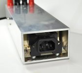
Transformer is mounted on a proto board, with p2p wiring. Please note that the Earth terminal from power entry module is soldered to a copper foil underneath one of the stand offs to ground the chassis.
Additional Burns potentiometer is used to set the output between 9-13V
I like to use 2 x 3 aluminum tubing for all my projects now. It simplifies chassis building as the main body of an enclosure consist of a single tube section cut to the required size, the end panels are really optional.
To reduce the amount of external screws, I'm using sub-plate to mount regulator board. The LM317 is installed on a sub-plate as well, as attaching screws inside the tube would be vary hard.
Transformer is mounted on a proto board, with p2p wiring. Please note that the Earth terminal from power entry module is soldered to a copper foil underneath one of the stand offs to ground the chassis.
Additional Burns potentiometer is used to set the output between 9-13V
Attachments
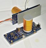
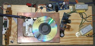
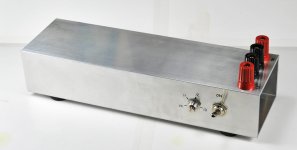
Such assembly slides into the tubing and I'm only using 4 screws to secure it (additional soft pad on top of transformer prevents any movement).
This particular PS is intended for use with field coil of Fertin driver.
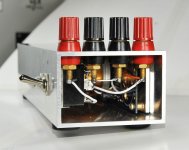
One pair of binding posts is for batteries attachment (in case batteries are not use, additional capacitor can be installed there), the other for driver connection. The toggle switch disconnects power to the driver, the potentiometer allows fine tuning of voltage output.
This particular PS is intended for use with field coil of Fertin driver.
One pair of binding posts is for batteries attachment (in case batteries are not use, additional capacitor can be installed there), the other for driver connection. The toggle switch disconnects power to the driver, the potentiometer allows fine tuning of voltage output.
Attachments
Peter -
Your work is brilliant. Very creative use of materials and parts.
If you wouldn't mind, I have a couple of questions...
1) why do you cut the square piece out of the middle of the board to mount the regulator? Aren't the small round holes in the middle of the resistor layouts for that???
2) do you make the board standoffs yourself??? or wwhere you you get them (p/n please) ???- they almost look like bronze flanged bushings.
3) finally is the brand of the large 4700 uF cap ???
Thanks,
- Ray
Last edited:
Ray, Thanks for the comments.
The round hole is too small for the screw head to go through, initially it was intended to improve air flow around resistor or heatsink, it can be also used as a mounting hole.
But now when you mentioned it, enlarging it would work fine. The cut out allows me to see better how regulator aligns on a mica pad, but it's not really critical.
The standoffs are indeed bronze flanged bushings, I bought them at local surplus outlet.
The cap is Roederstein (ROE); it's NOS but surprisingly good, in some applications better than BG.
- Home
- More Vendors...
- Audio Sector
- Universal Power Supply PCB