I'm late to the party on this thread and sorry because I do have the official schematic, parts list, and repair manual in pdf format for the Linn Valhalla board.
Here are some links to these files from my website; The Analog Dept.
http://www.theanalogdept.com/images/spp6_pics/Linn/valhalla_diag_l.pdf
and
http://www.theanalogdept.com/images/spp6_pics/Linn/Valhalla%20Parts%20List.pdf
and
http://www.theanalogdept.com/images/spp6_pics/Linn/Valhalla%20Repair%20Manual.pdf
-Steve
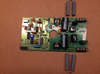
I present ..... the immortal valhalla
- caps are 150uF, 450 volts, 12,000 hrs at 105 degrees C
- rectifier is 1000 Volt, 6A
- NTC is 50 ohm, 430 Joules
- power resistors 7.5k at 10 watts each (15k in series)
I hope this outlasts me")
- caps are 150uF, 450 volts, 12,000 hrs at 105 degrees C
- rectifier is 1000 Volt, 6A
- NTC is 50 ohm, 430 Joules
- power resistors 7.5k at 10 watts each (15k in series)
I hope this outlasts me
Attachments
Last edited:
There is no absolute need for a 6 amp rectifier. 1.5 amp will do as the surge ratings are much greater and usually stated. No harm having better if it fits. I tried various caps from original 47 uF up to 440 uF. 220 uF 250 V ( seeing 160 V max ). It is arguable the output cap should be higher in voltage . 47 uF 400 V , however I never found a Valhalla that failed when the output cap. Specifically 220uF reduced PSU ripple to the minimum level. It is a significant -12 dB to about - 54 dB. Running Valhalla on a floating 230 or 115 isolation transformer takes it to about - 60 dB. The Linn motor has vibration effects.at about -40 dB. It could be thought original Valhalla is suitable. Not really as it causes very low frequency beat harmonics. This also argues that the 47 uF output capacitor could be 22 uF rather than 150 uF or 220 uF. 22 causes a slight drop in voltage which could be corrected. I wouldn't bother if 85 Vac or higher.
These upgrades should produce a better compromise than Lingo. The Valhalla has excellent technical specifications except for PSU ripple.
These upgrades should produce a better compromise than Lingo. The Valhalla has excellent technical specifications except for PSU ripple.
there are several other motor control units out for replacing Valhalla, - go to
Linn Lingo schematic
Linn Lingo vs. Dr. Fuß or Square-Wave vs. Sine Wave Oscillator for Motor Control
Trying to understand the Naim Armagedon power supply, please help
Armageddon clone VA size vs. regulation
Homebrew Motor Control Linn LP12 - Circuit Description wanted for Sine Wave Osc.
Armageddon clone for LP12 - why such a large transformer?
but nevertheless I want to know, if there are improvements possible on this board itself.
Maybe the replace of crystal oscillator by a sine wave version.
Thanks for comments.
The main problem is the motor. A slightly improved Valhalla has about 0.05% THD ( eg. replace 47 uF by 220 uF ). This looks to be unchanged by the motor as a voltage waveform due to low amplifier output impedance. If the current waveform is looked at via lets say 1 ohm resistor ( if possible less ) it is a nasty triangle wave of about 8% THD if I remember. Inside the motor is a magnetic circuit that looks identical to the waveform type. I could write pages and not really say more. The Linn motor is good of it's type. Voltage is the only tool we have once the basics are correct. The voltage dictates the current.
Like Triumph motorcycles of old less vibration is available at lower power. Vibration was also dictated by sweet spots of the vibration due to rotating masses and balance factors. A motor is not sinusoidal due to the connecting rod offset. If you plot crank rotation against stroke position it's very obvious. Firing on one cycle of four doesn't help either. This is all about understanding where a problem comes from. Triumph is an example of very bad design that was adorable so we persist. Triumph 6T was how the Police liked them. A practical T120.
The Rolls Royce Merlin looked to be a slightly wrong design until a simple question was asked. Did it work well in real life? Yes it did. It is said every Merlin was a prototype . Safe changes were made as months went by. As the engines were rebuilt frequently data was available quickly. The RR output gearbox looks too simple to work ( that alone could be 100 pages ). My feeling is it would last long enough to be replaced and gave simplicity. Radial engines used banks of 9 cylinders as ideal designs as it gave a better type of vibration. A V12 also is reasonable. Vibration can kill the engine and power output.
A 1943 German appraisal of the Merlin suggested it wasn't an ideal design until they tested it. RR had used many little tricks to get it to work. I have to say I don't really like the Merlin except it was good enough. RR can make anything work. In some ways the Napier Lion was a better design if like the Benz it was inverted. Napier gave up chasing RR as best I know. The Napier looks even worse on paper except the crankshaft is short and very stiff. Bristol were genius designers.
If I have stimulated looking at aircraft engines here are a few curious ideas. Say the bore and stroke is 5 to 6 inches and you won't be very wrong. The motors mostly go too fast for direct coupling ( not much curiously ). The Merlin looks too primitive when the output gearbox. It's V is determined by getting speed from the aircraft and allowing the pilot to see. In a nutshell that's the basics. Fuel and superchargers being important. The Merlin used overhead cam valves for reasons I can not understand. I suspect as it is easy to sell to customers and easy enough to do. I learned plenty from engine types that relates to turntables. Marine diesels also where vibration is a big nasty problem. They sit next to electronics in British libraries in section 621.... As a Covid pursuit not too bad. I think you will have great respect for the engineers.
In analogy with radial aircraft engines hysteresis motors have better fundamentals. I read recently hysteresis types are being revisited in electric cars. They would make hopeless electric clocks as to why they may have been overlooked for so long. If lightly loaded they are not too bad on speed and have about 0.4 % THD.
A lamp type Wien oscillator could be used as in Thorens TD125. 28V 40 mA lamps work well ( from aircraft ). They need to be in a sealed box away from light or heat and take a while to settle ( 20 seconds ? ). I have seen better than 0.01% THD from a simple Wien type. NE5534 seems ideal as it won't mind the load. I would expect a slightly softer sound although measurements won't say why. Feed the signal in after the last square wave divider. 10 nF NPO and circa 318 K will give 50 Hz. Often NPO and MRS25 resistors or similar ( 50 ppm ) gives crystal like stability. If a resistance of perhaps 100R is used in series with the lamp it might help. If a NE5534 I doubt it would matter. Wiens either work or don't work. They give 90% even when not ideal. It is said when 50 Hz the lamp even cools on cycles and prevents the same as 1 kHz reading ( i.e 0.05% 0.005% ). Who knows. 1937 circuit.
An idea I had and is a DC to DC converter as a simple switch-mode device. 12VDC in 300VDC out. I assume a Valhalla for this . This avoids the 50.5 +50 Hz beat you can get. The circuit below is just to give a basic idea. The 555 idea looks simple enough. Use a >1 meter cable to the turntable I feel. In my opinion this could be a very big difference. It should be cheap to do. 10VA I guess.
12v to 300v dc-dc converter circuit - ElecCircuit.com
> every Merlin was a prototype . Safe changes were made
While Merlin had many jobs, the critical job was stopping bombers intent on mass destruction and incidental death. In this role a 500 hour service life was absurd; under 50 hours before crash more typical. So things like bearing life and vibration fatigue were not optimized, in favor of fast production and more peak power.
> The Merlin used overhead cam valves for reasons I can not understand.
On a Vee engine, crossflow, pushrods would foul the intake (or exhaust) ports. Ford had a series of sucky sedan engines with this flaw. If the ports are on one side, such as the Gypsy Moth mill, it's not great but OK, but ill-suited to Vee plan. (See the mess inside the Vee of the first Cadillac V-16, or the poor ports of the first Ford V8.)
The weight of the single (per bank) cam drive up-shaft may be less than the sum of 24 pushrods per bank.
> The motors mostly go too fast for direct coupling ( not much curiously ).
There are two points which must run near but not-too-near the speed of sound. Propeller tips, and intake port air. If you have too few pistons (1 to 4), the motor wants to be about the size of the propeller and run slow. If you have lots of pistons, the motor wants to be small and run faster than a propeller big enough to absorb its power. So gearbox.
The gearbox is heavy and often as troublesome as the motor. And if the motor is run slow the cost of parts and time between overhauls is improved. So a wide range of light planes runs prop direct on crank.
My book on Aircraft Engines by Judge 1942 likes sleeve valve engines to reduce exhaust temperature. He like me sees everything else as less good. In car engines this never became reality. Fokker Wolfe 190 with a Bristol engine would have been interesting. It could have been a little faster.
300 VDC for the Valhalla seems a great idea. It must be battery driven from a step up converter. Linn stated ( to me ) that the beat frequency was a serious defect of Valhalla. It's about - 41 dB with 47uF and - 54 dB 220uF. -60 dB if on a floating transformer. In the UK a 230 to 110VAC can be used if the Valhalla is adjusted to 115V. That is cheaper.
300 VDC for the Valhalla seems a great idea. It must be battery driven from a step up converter. Linn stated ( to me ) that the beat frequency was a serious defect of Valhalla. It's about - 41 dB with 47uF and - 54 dB 220uF. -60 dB if on a floating transformer. In the UK a 230 to 110VAC can be used if the Valhalla is adjusted to 115V. That is cheaper.
Last edited:
300 VDC for the Valhalla seems a great idea. It must be battery driven from a step up converter. Linn stated ( to me ) that the beat frequency was a serious defect of Valhalla. It's about - 41 dB with 47uF and - 54 dB 220uF. -60 dB if on a floating transformer. In the UK a 230 to 110VAC can be used if the Valhalla is adjusted to 115V. That is cheaper.
The Phoenix Falcon PSU used a flyback converter running at ~30kHz to do this but it produced a tightly regulated ±170VDC. The output amp was an Apex power opamp; the output was directly coupled (no cap or xfmr) and very low impedance (<.01R). It also made the PSU very compact, about the size of a pack of cigarettes with 5W capability. The amp would actually do 10W, but the case was so small there wasn't an adequate heatsink for that power level.
The sinewave generator was a xtal controlled 28bit DDS with frequency resolution of 1/800 Hz and distortion <0.02%.
That's very interesting.
I just read my notes. 330 VDC ( typical of UK ) seems about ideal if no oscilloscope to hand to avoid clipping. Use 230VAC input. DC will flow through the rectifier without modification. As it's low current no harm using one side of the bridge rectifier. I think the motor uses 1VA. 10 VA covers the 15K resistors that get very hot. The 50Hz + X Hz is the only real problem. The LP12 motor is best of a not so good bunch. I never found an ideal substitute.
The Valhalla I measured was very low distortion at <0.05%. Motor current is nearer a triangle wave.
From memory the 115 VAC side is a voltage multiplier which would block DC. I am reasonably sure I have used DC to Valhalla this way. I doubt I need say some danger is involved so leave well alone if unsure. One can introduce DC after the rectifier if required.
...Judge 1942 likes sleeve valve engines....
Rolls-Royce Crecy - Wikipedia
Nahum, A., Foster-Pegg, R.W., Birch, D. The Rolls-Royce Crecy, Rolls-Royce Heritage Trust. Derby, England. 1994 ISBN 1-872922-05-8
If people don't mind two stroke engines are something Judge really likes. He is very enamoured with the Junkers designs made under licence by Napier ( Deltic is generic ). Being wartime, what objectivity! The Germans also were full of praise for our engines ( They love the Napier Lion of 1920s, they suspected it better than the RR Eagle that became Merlin ). Judge points out that the four stroke has better outcomes. The efficiency of diesel radial engines is probably marginally better than jets of the era. Alas the need to service the engines every week if a transatlantic aircraft means they never became reality, petrol types had these disadvantages also but were well understood. The important weight reduction in diesel fuel economy was the advantage and no reliability issues. The Junkers engine was a gem. It neatly fits in a wing and is good on vibration ( vibrations kills parts ). Diesel would probably stand higher boost pressure without exhaust valve problems. The power output for a given weight was as good as petrol types. Boost is about getting the engine to work better as much as raw power. 33 000 ft is usually a target for more comfortable travel and good fuel use. Boost allows that. A jet is the logical development.
My maths teacher Chris Bartrum built the Whittle engine in the science museum. A very nice man. He never taught me much maths really. He taught me persistence. We often used aircraft for examples when electrical engineering was the subject! Being young I never asked why.
8 inch stroke compared with 6 inch petrol was the only difference on a diesel type if optimum sized and not just adapted petrol. Bore would be circa 6 inch for both. If a sleeve valve the engine would be DC3 size.The diesel might offer direct coupling. Probably 4 x 18 cylinder radials if a transcontinental type.
Some extra Valhalla data. Linn told me the Valhalla was class AB and Lingo A. The circuit diagram shows R24 as 22R. The sample I had w as 33R at 375 mV. That is 11.4 mA standing current ( mostly voltage independent due to current mirror ). The circuit looks like a mini JLH class A amplifier. 319 VDC with 157 VDC centre voltage. 1.82 watts dissipation per BUX84 NPN. Linn did admit they didn't entirely understand the circuit. I doubt it is class AB. I haven't measured the motor current. I would guess it to be about like the standing current at 100 VAC. 10 mA rms? I have seen a Valhalla give a notch in the output so it must be on the edge. It looked nicer through the blue phase when so due to the 0.22 uF.
If thinking about the Airpax motor remember the inductance is in series with the considerable coil resistance. What you see as the Valhalla output voltage is what the amplifier is doing rather than the motor. The vibration you feel is the magnetic circuit plus phase error on blue phase ( select the 0.22 uF ). There is no harm improving the distortion but if it works it likely is output impedance helping. You could digitally record the motor waveform . This could be used as pre-distortion as it is repetitive. It might just make a difference. If you feed the Airpax with a square-wave it works almost a well as a sine-wave. This is because the motor works as a powerful filter. Try the Airpax at 200 Hz. It won't want to know. 67.5 Hz is fine.
- Status
- This old topic is closed. If you want to reopen this topic, contact a moderator using the "Report Post" button.
- Home
- Source & Line
- Analogue Source
- Linn Valhalla