Because Linn's LINTO in used condition is more expensive than a KAIRN this idea rises up and was realized several times. Additional sound quality is better than from LINTO and an additional benefit is the possibility of using also the MM input. A disadvantage is the fact, that MM/MC cannot be use at the same time, because therefore a switch selector would be necessary.
Follow steps are to perform:
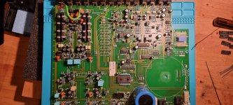
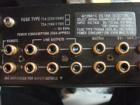
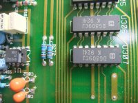
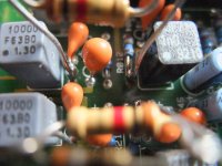
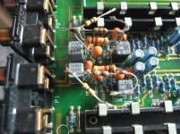
1) Prepare output sockets "MATRIX" for line out of this phono preamp section to avoid any influence by C-MOS switching effects:
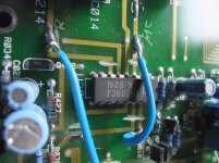
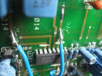
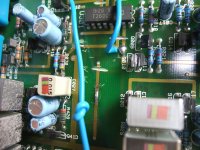
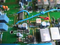
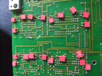
- Cutting conductor track from node R072/272 as well as C018/218 and C019/219 (L/R) to PIN3/PIN14 of U307 (DG309CJ, C-MOS source selector) - go to image No 1, 2 and 3.
- Use this existing output sockets to which these conductor tracks are connected as line-out of this phono preamp
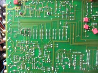
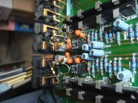
2) Bypass C-MOS switch for switching between MM/MC by cutting the conductor track to IC U301 (DG309J):
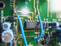
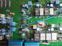
- cutting the conductor from C014/214 (output MC input stage) to PIN 3/6 (L / R), U301 - go to image No. 4,5 and 7
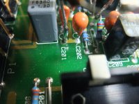
- cutting the conductor path from node C027/227 and R043/243-R070/270 (output MM level) to PIN 11/14, U301 - go to image No. 4,5,6,7 and 8
- cutting the conductor from the base Q10/210 (input, phono output stage) to PIN 10/15, U301- go also to image No. 4,5,6,7 and 8
- soldering a cable from the input of the phono output stage
- either to the output of the MC input stage - was done at this example, go to image No. 4-9 and 10 (solder side view), 2x blue cable
- or to the output of the MM input stage (short red cable ends provided as marking at the output of the MM input stage, go to image No. 8 and 9)
3) disconnect front board from the main board by removing the plug
Now sound quality is much more better (mainly due the absence of RF from the operating/MCU board and because no longer C-MOS switches in the signal pad).
Follow steps are to perform:
1) Prepare output sockets "MATRIX" for line out of this phono preamp section to avoid any influence by C-MOS switching effects:
- Cutting conductor track from node R072/272 as well as C018/218 and C019/219 (L/R) to PIN3/PIN14 of U307 (DG309CJ, C-MOS source selector) - go to image No 1, 2 and 3.
- Use this existing output sockets to which these conductor tracks are connected as line-out of this phono preamp
2) Bypass C-MOS switch for switching between MM/MC by cutting the conductor track to IC U301 (DG309J):
- cutting the conductor from C014/214 (output MC input stage) to PIN 3/6 (L / R), U301 - go to image No. 4,5 and 7
- cutting the conductor path from node C027/227 and R043/243-R070/270 (output MM level) to PIN 11/14, U301 - go to image No. 4,5,6,7 and 8
- cutting the conductor from the base Q10/210 (input, phono output stage) to PIN 10/15, U301- go also to image No. 4,5,6,7 and 8
- soldering a cable from the input of the phono output stage
- either to the output of the MC input stage - was done at this example, go to image No. 4-9 and 10 (solder side view), 2x blue cable
- or to the output of the MM input stage (short red cable ends provided as marking at the output of the MM input stage, go to image No. 8 and 9)
3) disconnect front board from the main board by removing the plug
Now sound quality is much more better (mainly due the absence of RF from the operating/MCU board and because no longer C-MOS switches in the signal pad).
Attachments
-
 Linn KAIRN MATRIX=Phono-Out.jpg1,023.6 KB · Views: 457
 -
 Linn KAIRN R072,272,C018,218,C019,219 - PIN3,14 U307-I.jpg1,014.5 KB · Views: 483
 -
 Linn KAIRN R072,272,C018,218,C019,219 - PIN3,14 U307-II.jpg1,003.9 KB · Views: 409
 -
 Linn KAIRN C014,214 trace U301 PIN 3,6-I.jpg1,015 KB · Views: 435
 -
 Linn KAIRN C014,214 trace U301, PIN 3,6-II.jpg994.2 KB · Views: 365
 -
 Linn KAIRN C027,227 trace U301, PIN 11,14.jpg1,006.7 KB · Views: 235
 -
 Linn KAIRN C027,227 trace U301, PIN 11,14-II.jpg1,003.3 KB · Views: 234
 -
 Linn KAIRN MM out red cable-I.jpg1,002.4 KB · Views: 245
 -
 Linn KAIRN MM out red cable-II.jpg1 MB · Views: 257
 -
 Linn KAIRN U301, PIN10,15, trace Q10,210-II.jpg1 MB · Views: 392
Last edited:
Prepare for adding external Load Resistors
Additional step for using even MC cartridges who need low impedance load is the preparation for retrofitting additional load resistors (cartridge load) at the MC input:
- desolder C001/201 (input) and R012/R212 (GND) on one side, solder in the 1K resistor as prepared in the images and solder the components - that are desolder before - on one side to the lead wires of this resistor.
- Solder the necessary load resistors to the 1K resistor in parallel (39 ohms and - if wanted additional 47 ohms for approximately 22 R at whole - this is an example for cartridges like AT-OC9 and some Ortofon models from the "QUINTETT" series).
Attachments
Nice idea, but the mods on the PCB are quite brutal, and hardly reversible. I think it would suffice to desolder DG309s (probably U301 and U307 would suffice), solder sockets in their place, then simply instead of U301 insert jumpers in the right places (MM or MC, depending what's required). Then we can even leave the control board connected and have a working line-pre and separate phonostage in one box (in case that's of any use for someone).
I'm currently trying to restore my newly bought old-and-almost-working Kairn to its' original glory, once (if) finished I'll try the fully reversible mod and post results.
I'm currently trying to restore my newly bought old-and-almost-working Kairn to its' original glory, once (if) finished I'll try the fully reversible mod and post results.
Nice idea, but the mods on the PCB are quite brutal, and hardly reversible. I think it would suffice to desolder DG309s (probably U301 and U307 would suffice), solder sockets in their place, then simply instead of U301 insert jumpers in the right places (MM or MC, depending what's required). Then we can even leave the control board connected and have a working line-pre and separate phonostage in one box (in case that's of any use for someone).
I'm currently trying to restore my newly bought old-and-almost-working Kairn to its' original glory, once (if) finished I'll try the fully reversible mod and post results.
No. Except, when the focus is on collectibles and cutter traces at the copper rails resp. conductor tracks (which can easily be reconnected with wire bridges) destroy the collector's value (isn't the case at Linn's Kairn and LK-1).
BTW - Unsoldering the DG309 IC's is extremely difficult because the pins are bent over.
Regardless of this, jumpers in IC sockets can cause contact problems - this only makes sense if creating the genuine condition is definitely carried out again.
Last edited: