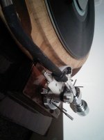
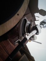
I am waiting for bits to get back to making the servo linear so while I had nothing to do I decided to make some modified parts for my EPA100.
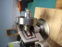
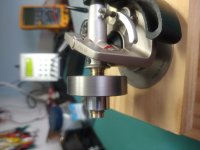
The stub is solid brass and the CW is stainless steel with an aluminium locking collar. The additional mass of the SS CW also moves the centre of the CW closer to the pivot. One thing I didn't like with the EPA is the loose fit of the stub into the arm pillar. The new brass stub is machined to a close slip fit and the CW M12 x 1.25 thread is precision machined so there is no slop in the CW, which is then locked with the aluminium locking ring.
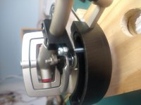
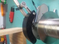
I also machined a damping trough which is fixed to the underside of the arm clip so in the unlikely event I decide to sell the EPA removing the CW and damping system leaves no marks on the arm.
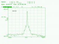
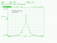
The plots are 300Hz tone band 6 on the HIFI News test LP. The 8.5Hz sidebands are totally gone. I was not expecting this to be an upgrade I thought the change would be inaudible but this is not the case as the measurements show.
I still need to dial in the damping but listening to the TT now.
.
The stub is solid brass and the CW is stainless steel with an aluminium locking collar. The additional mass of the SS CW also moves the centre of the CW closer to the pivot. One thing I didn't like with the EPA is the loose fit of the stub into the arm pillar. The new brass stub is machined to a close slip fit and the CW M12 x 1.25 thread is precision machined so there is no slop in the CW, which is then locked with the aluminium locking ring.
I also machined a damping trough which is fixed to the underside of the arm clip so in the unlikely event I decide to sell the EPA removing the CW and damping system leaves no marks on the arm.
The plots are 300Hz tone band 6 on the HIFI News test LP. The 8.5Hz sidebands are totally gone. I was not expecting this to be an upgrade I thought the change would be inaudible but this is not the case as the measurements show.
I still need to dial in the damping but listening to the TT now.
.
Attachments
-
 IMG_20210105_170409995.jpg676.8 KB · Views: 354
 -
 IMG_20210105_170359238.jpg794.2 KB · Views: 354
 -
 IMG_20210105_105647337.jpg705.3 KB · Views: 323
 -
 IMG_20210105_105758814.jpg700.7 KB · Views: 345
 -
 300Hz_CW_damp2.jpg210.8 KB · Views: 145
 -
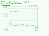
 300Hz_OEM.jpg205.7 KB · Views: 136
 -
 300Hz_CW_damp.jpg209.5 KB · Views: 140
 -
 300Hz_OEM1.jpg219.1 KB · Views: 347
EPC205mk3U with a Jico SAS/R stylus. I also plan to do the same test with a Stanton 881s to see if the results are similar. They were certainly repeatable with the EPC205.
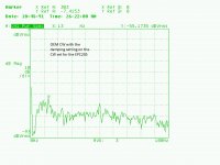
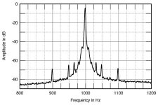
It was changing the CW that dropped the 8.5Hz sidebands, viscous damping narrowed the fundamental where the sidebands were so the 13.5Hz sidebands are more visible. Next is to investigate what is causing the 13.5Hz.
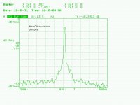
This plot is with new CW no damping. The plot above with the new CW has only a very small amount of damping.
It was changing the CW that dropped the 8.5Hz sidebands, viscous damping narrowed the fundamental where the sidebands were so the 13.5Hz sidebands are more visible. Next is to investigate what is causing the 13.5Hz.
This plot is with new CW no damping. The plot above with the new CW has only a very small amount of damping.
Attachments
Ya the bearings can be a pain. I've had more than a few through where there was a single chipped ball that caused inconsistent results that were very difficult to track down. Sadly tedious visual inspection is the only way to really know.
Did you use the rubber gasket with the original CW? Do you know if it still has full charge of damping fluid? Are you going to experiment with adding mass to the original CW to see if what you're measuring can be attributed to the attachment mechanism or the shift in EM?
Did you use the rubber gasket with the original CW? Do you know if it still has full charge of damping fluid? Are you going to experiment with adding mass to the original CW to see if what you're measuring can be attributed to the attachment mechanism or the shift in EM?
The issue I had was antiskate applied to the arm with the antiskate turned off, re-dressing the wiring fixed this. The arm is now free and smooth in the horizontal plane.
What rubber gasket? I didn't know there was one and the service manual doesn't show it.
I don't know if the damping fluid is full or not I haven't opened the CW and there have been no signs of fluid leakage. Have you opened the CW and if so what is the best way to go about it.
I did think about EM this is why I made the new CW heavier so it is closer to the pivot although the calculated EM does not change much because the largest contributor is the cartridge/headshell.
IMO the reason the CW lowered the TA/Cart resonance sidebands is the close fit. In a production environment Technics would need to size the hole and stub for the worst cast tolerance, So if the hole was at min and the CW stub max tolerance they would still fit. In my case I machined the stub for a very precise slip fit. I had to de-bur and polish the stub so it fit.
Even so the 8.5Hz sidebands on a 300Hz fundamental are -47dBv down which is better than the LP12 Ekos Arkiv measured by Stereophile at -41dB at 1kHz.
Attachments
Hi, warrjon
Very nice work !!! You may be able to get further CW improvement by making it 2 pieces. You can use an inner part that goes on the threaded shaft and outer mass of the counterweight into a teardrop shape using a tungsten / copper alloy ( ebay ). this will allow you to lower the CW mass closer to the stylus height. This copper alloy is much heavier then stainless steel. Just make the outer counterweight a sliding fit over the inner threaded part using a through nylon / delrin bushing. Should be fairly easy to make. I used this method on my DIY linear tracking arm. I suck with computers and pictures but I am sure you get my point. Just my .02 cents--Good Luck.
Joe
Hi Joe,
Thank for input. This was a time fill project while I wait for parts for my Servo Linear arm and Gunmetal bronze platter blanks. Although the lessons learnt will carry over to the SLTA.
I did think after I made this about making the main CW slide on the stub and lock then a screw in the end of the stub for fine adjustment.
Cheers.... I know SME use balsa. I will pull it apart and have a look, just can't help myself.
You’ve a 100MK2 as well? The 100 doesn’t use anything in the tube.
Excellent work with hand tools...
Yes too much damping restricts the movement of the arm. I made the screw height adjustable so I can vary damping.
I used a Dynamic Signal Analyser to set it up and you can see as damping is added the bottom of the fundamental narrows until you get too much then sidebands jump out of nowhere.
I have seen the Townsend, I like the damping at the headshell and I'm going pinch the idea for next servo linear tracker.
- Home
- Source & Line
- Analogue Source
- Technics EPA100 modifications