Synchronous Motor Driver for Dual CS522 or CS505 using SM100-1 motor
Much has been written about the Synchronous motor power supply for turntables. Especially for Linn, Thorens and VPI type turntables, these turntables enjoy a dedicated driver that give them a very good name and also some ridiculous prices. Many turntables below the $1500 price mark using AC motor still rely on a simple capacitor phase delay scheme. The disadvantage is well known : vibration. And hence degraded sound. A motor driver like the case of a Linn Lingo or etc, are too complicated and Expensive. This project shows a motor driver that is cheap to build, with readily available parts, and demonstrated to significantly eliminate the vibration on a Dual SM100-1 motor. The circuit is nothing new, but the investigation shows significant improvement on other turntables that uses AC motor. (eg. Rega)
Using a DC motor to replace the AC motor may not be a final answer. DC motor control is complicated, and may even involve mechanical modification for existing motor mounting. The control scheme may involve a feedback tacho generator, which can also be a problem to implement.
The following system diagram is inspired by Hans Polak in his 2016 post on Optimally driving a (VPI) synchronous turntable motor. I have learned a lot from Hans, Thank you! I have also done some investigations using the Dual CS522 motor and have some interesting findings.
The system diagram explains the concept and strategy
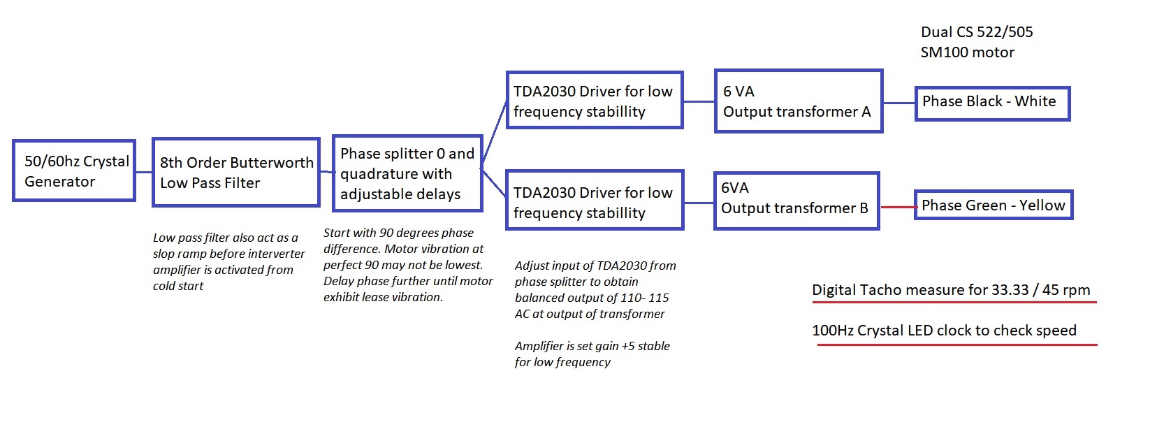
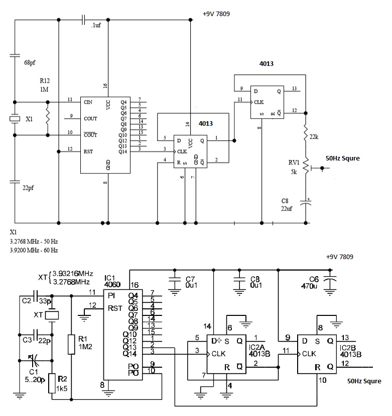
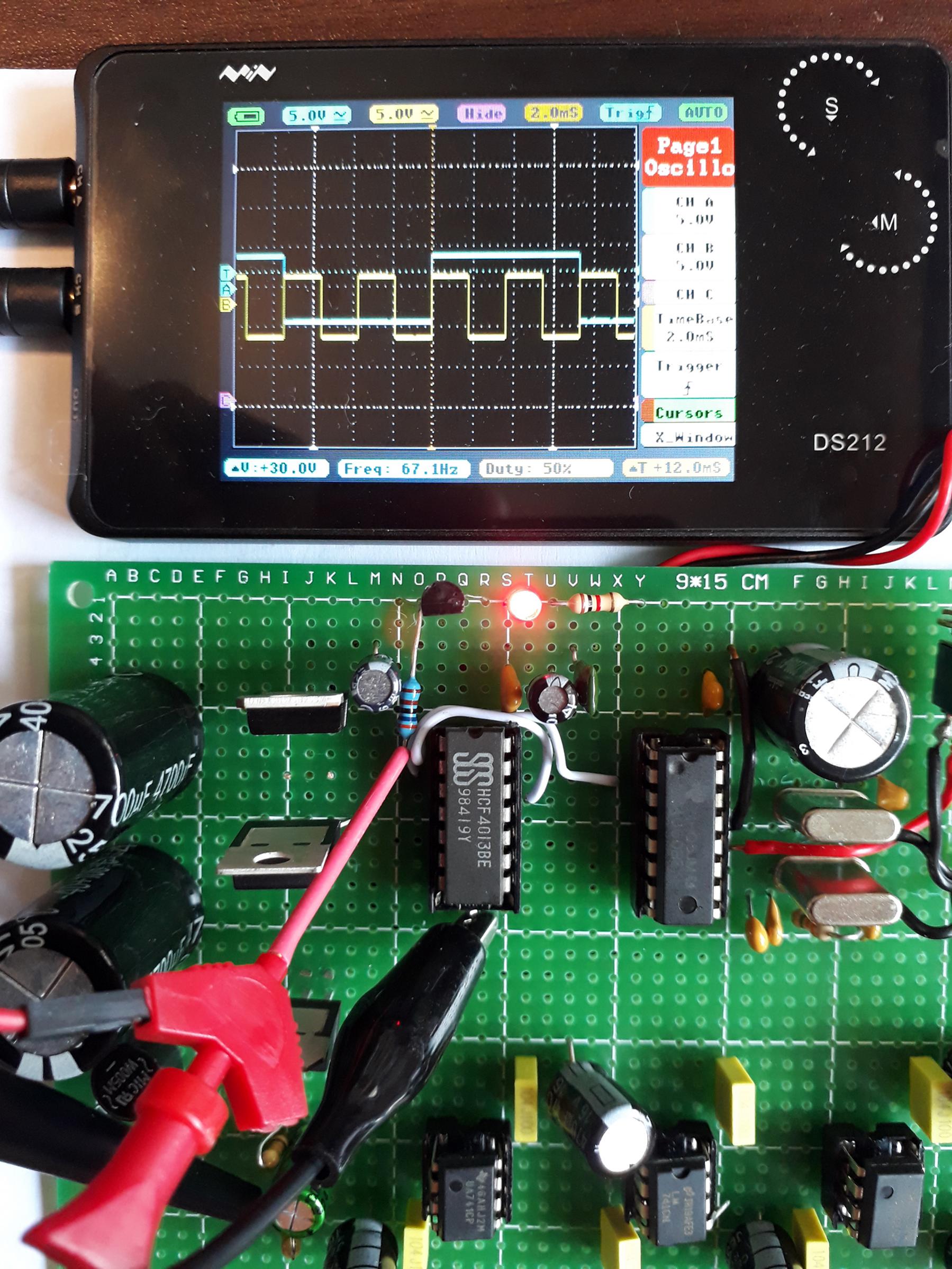
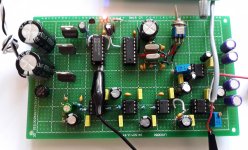
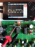
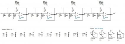
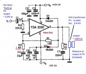
The Clock generator is a standard well known 3.2768Mhz Crystal Clock circuit, under going divisions to get 50Hz or 60Hz. The SM100 is a 16 pole motor, so 50hz gives 375 rpm rotational speed. This drives the pulley systems in many CS522 or 505 family turn tables. I verified that the SM100 is able to run at higher frequency of 75hz, and directly drives the platter to give 45rpm on the Dual. However, I want to make use of the mechanical selections available on the Dual, so I focus on getting a very stable 375 rpm with little or no vibration from the SM100 motor. The 4013 D flip flop providing division by 2, twice, is a sensitive circuit, that needs care in soldering and securing to give a stable operation.
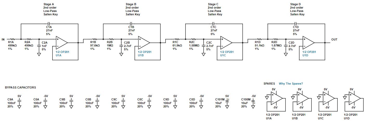
Filtering is done by an 8th order Butterworth low pass filter. Design is automated using the Anlog Device wizard here Filter Wizard | Analog Devices
The corner frequency is selected at 60Hz, and stop band before the first square wave harmonic of 150Hz for 50Hz. This filter circuit is easy to build and act as a ramp during start up.
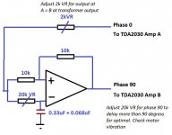
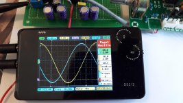
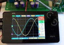
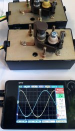
The phase generator can vary the delay from 90 degrees to even further. There were some interesting findings : Delay to further such as 95 , the motor will reach a sweet spot with very little vibration. Advancing the phase to less than 90, of course, will generate more vibration. I cannot explain the delay. This could be physical construction of the SM100 motor. I have checked 3 different SM100 motors, and each has a different sweet spot. Some manual adjustment is needed. Visually, I used the scope to check the delay, but I use my palm to feel the vibration. Delaying the phase further slightly gives a better result.
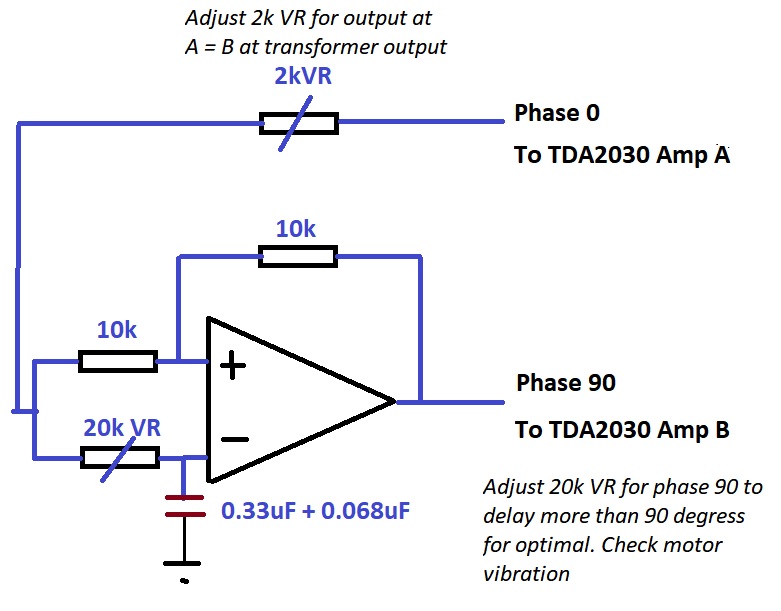
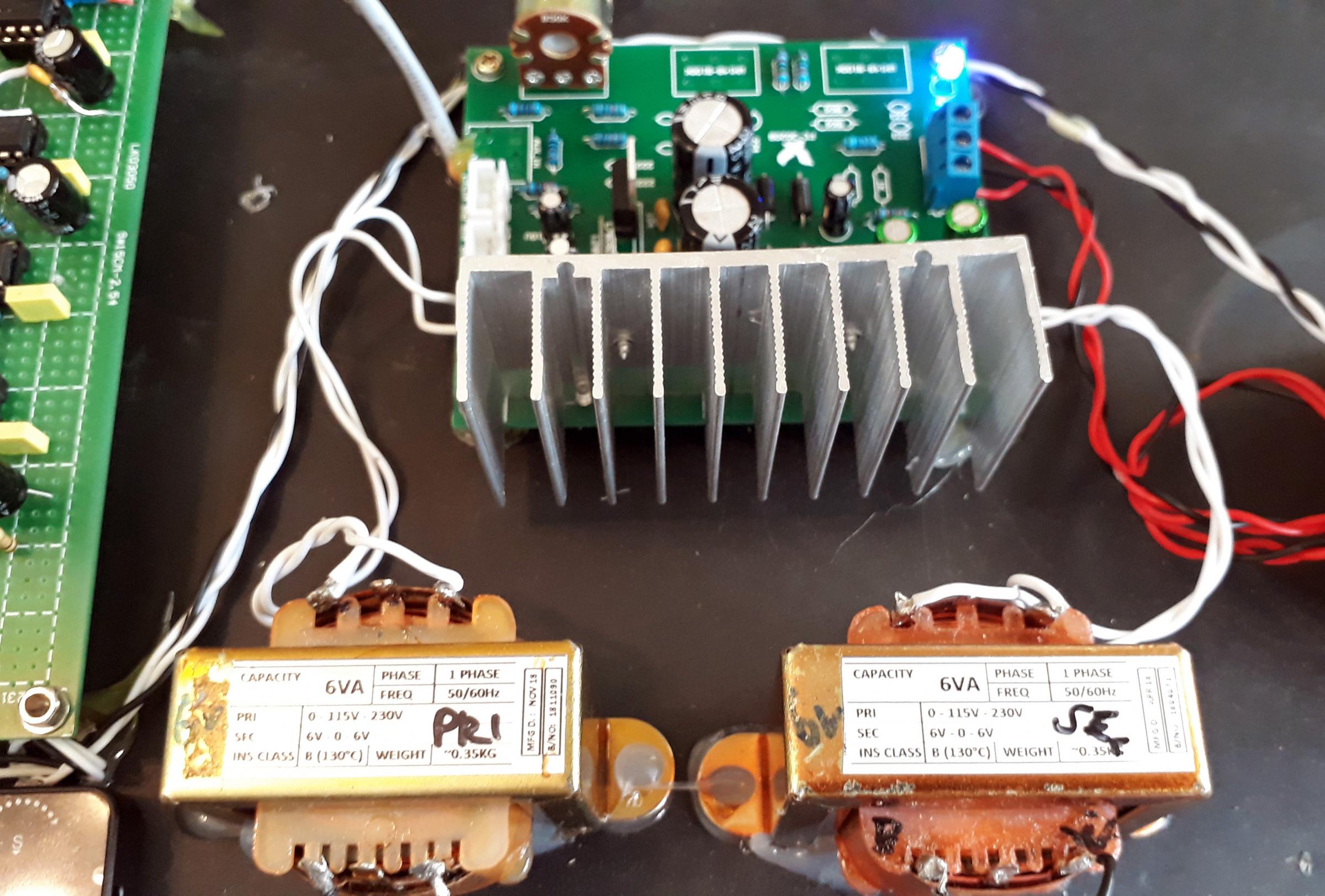
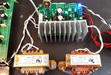
The inverter driver is a simple TDA 2030 Kit, which is sold in Ebay as a stereo subwoofer driver for less than $10 for a built up board. I have changed the gain setting feedback resistor to 5k ohms and the ref resistor 1 k ohms. This amplifier is gain stable and operates at about 55C for extended hours with no further heat sinking required.
The output transformers are a pair of 6VA EI type transformers. They are readily available. I have chosen the 230V type so there are more copper and iron in the transformer. The SM100-1 is basically a 115V motor, and in countries like UK the voltage is dropped via a power resistor (which can run very hot within a plastic casing). The 230V type transformer appear to make the TDA2030 cope better in the stepping up of voltage to 115V. I recommend running the motor at 115V and less than 100V the motor may not have sufficient torque.
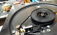
The Dual CS522 or 505 in its original form, has 3 rubber stands that can cope with a vibrating AC motor. This upgrade makes the motor operate as if it is a DC motor. Hence there will be reduced disturbances to the arm. Note that due to the age of the motor, it is recommended to service the motor with a new rotor and new sintered bushings soaked in ester type machine oil. The air gap of the rotor to the stator can be confirmed by inserting stripes of A4 paper during installation. This will ensure there is a uniform air gap, a key to low vibration motor.
After installation, I found that the motor phase sweet spot needed to be further adjusted when it is loaded. The delay was even further than it was running in no load condition. I have yet investigated why this is so. If someone can explain this I will be grateful.
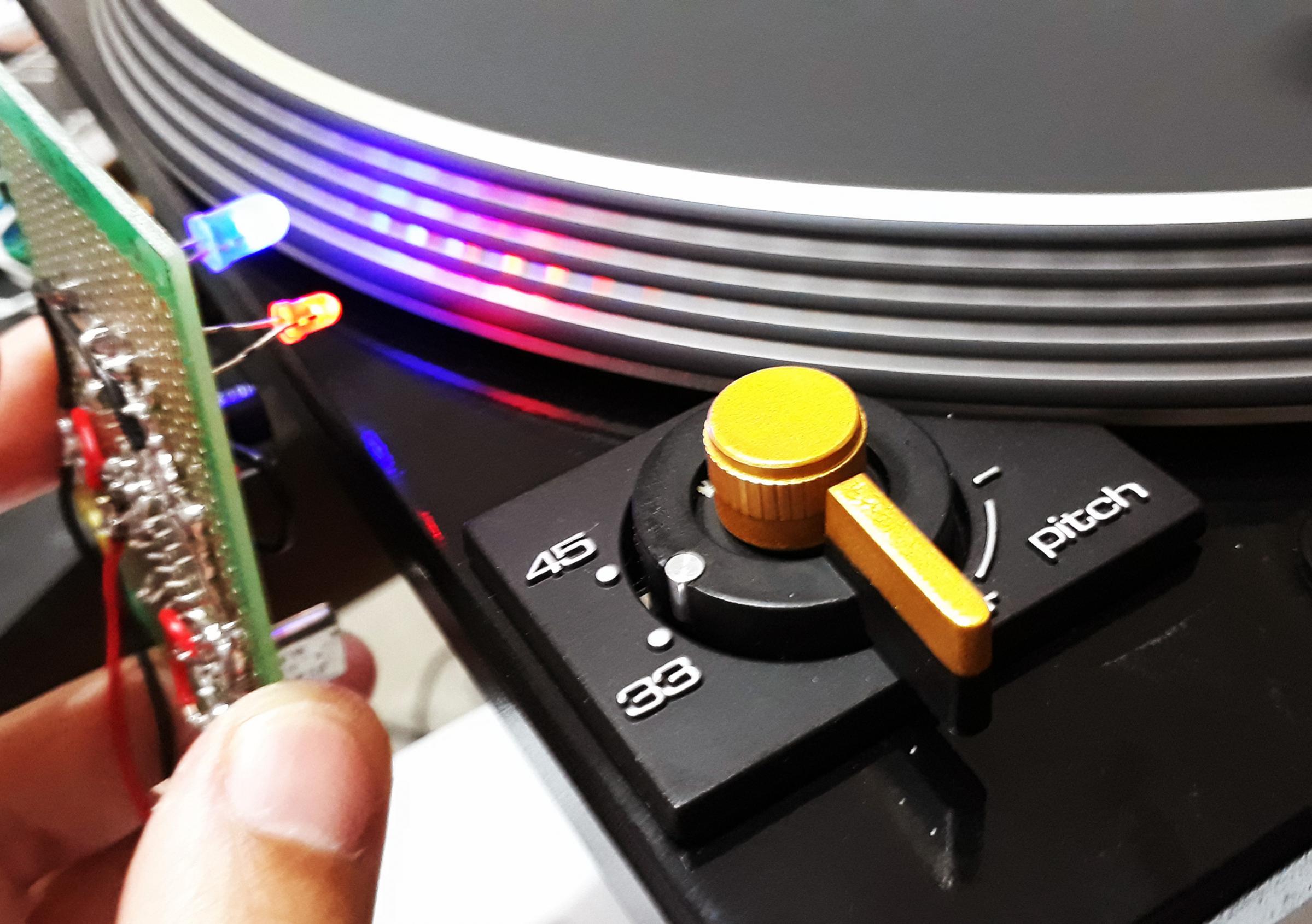
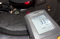
Touching the motor SM100, can hardly feel it is vibrating when in operation. The motor speed is rock solid at 33.33 or 45 rpm. Note that the Dual motor pinion needs to setup properly with reference to Dual service manual, in order to allow the speed adjust and speed select to work flawlessly.

I could not hear any motor noise using the stethoscope on the turntable when it is turning. The next step is to mount a new CS505-4 type arm, replace the 5 ball bearings on the support using ceramic type, and verify using listening test to compare with a stock CS522 turntable.
Much has been written about the Synchronous motor power supply for turntables. Especially for Linn, Thorens and VPI type turntables, these turntables enjoy a dedicated driver that give them a very good name and also some ridiculous prices. Many turntables below the $1500 price mark using AC motor still rely on a simple capacitor phase delay scheme. The disadvantage is well known : vibration. And hence degraded sound. A motor driver like the case of a Linn Lingo or etc, are too complicated and Expensive. This project shows a motor driver that is cheap to build, with readily available parts, and demonstrated to significantly eliminate the vibration on a Dual SM100-1 motor. The circuit is nothing new, but the investigation shows significant improvement on other turntables that uses AC motor. (eg. Rega)
Using a DC motor to replace the AC motor may not be a final answer. DC motor control is complicated, and may even involve mechanical modification for existing motor mounting. The control scheme may involve a feedback tacho generator, which can also be a problem to implement.
The following system diagram is inspired by Hans Polak in his 2016 post on Optimally driving a (VPI) synchronous turntable motor. I have learned a lot from Hans, Thank you! I have also done some investigations using the Dual CS522 motor and have some interesting findings.
The system diagram explains the concept and strategy
The Clock generator is a standard well known 3.2768Mhz Crystal Clock circuit, under going divisions to get 50Hz or 60Hz. The SM100 is a 16 pole motor, so 50hz gives 375 rpm rotational speed. This drives the pulley systems in many CS522 or 505 family turn tables. I verified that the SM100 is able to run at higher frequency of 75hz, and directly drives the platter to give 45rpm on the Dual. However, I want to make use of the mechanical selections available on the Dual, so I focus on getting a very stable 375 rpm with little or no vibration from the SM100 motor. The 4013 D flip flop providing division by 2, twice, is a sensitive circuit, that needs care in soldering and securing to give a stable operation.
Filtering is done by an 8th order Butterworth low pass filter. Design is automated using the Anlog Device wizard here Filter Wizard | Analog Devices
The corner frequency is selected at 60Hz, and stop band before the first square wave harmonic of 150Hz for 50Hz. This filter circuit is easy to build and act as a ramp during start up.
The phase generator can vary the delay from 90 degrees to even further. There were some interesting findings : Delay to further such as 95 , the motor will reach a sweet spot with very little vibration. Advancing the phase to less than 90, of course, will generate more vibration. I cannot explain the delay. This could be physical construction of the SM100 motor. I have checked 3 different SM100 motors, and each has a different sweet spot. Some manual adjustment is needed. Visually, I used the scope to check the delay, but I use my palm to feel the vibration. Delaying the phase further slightly gives a better result.
The inverter driver is a simple TDA 2030 Kit, which is sold in Ebay as a stereo subwoofer driver for less than $10 for a built up board. I have changed the gain setting feedback resistor to 5k ohms and the ref resistor 1 k ohms. This amplifier is gain stable and operates at about 55C for extended hours with no further heat sinking required.
The output transformers are a pair of 6VA EI type transformers. They are readily available. I have chosen the 230V type so there are more copper and iron in the transformer. The SM100-1 is basically a 115V motor, and in countries like UK the voltage is dropped via a power resistor (which can run very hot within a plastic casing). The 230V type transformer appear to make the TDA2030 cope better in the stepping up of voltage to 115V. I recommend running the motor at 115V and less than 100V the motor may not have sufficient torque.
The Dual CS522 or 505 in its original form, has 3 rubber stands that can cope with a vibrating AC motor. This upgrade makes the motor operate as if it is a DC motor. Hence there will be reduced disturbances to the arm. Note that due to the age of the motor, it is recommended to service the motor with a new rotor and new sintered bushings soaked in ester type machine oil. The air gap of the rotor to the stator can be confirmed by inserting stripes of A4 paper during installation. This will ensure there is a uniform air gap, a key to low vibration motor.
After installation, I found that the motor phase sweet spot needed to be further adjusted when it is loaded. The delay was even further than it was running in no load condition. I have yet investigated why this is so. If someone can explain this I will be grateful.
Touching the motor SM100, can hardly feel it is vibrating when in operation. The motor speed is rock solid at 33.33 or 45 rpm. Note that the Dual motor pinion needs to setup properly with reference to Dual service manual, in order to allow the speed adjust and speed select to work flawlessly.
I could not hear any motor noise using the stethoscope on the turntable when it is turning. The next step is to mount a new CS505-4 type arm, replace the 5 ball bearings on the support using ceramic type, and verify using listening test to compare with a stock CS522 turntable.
Attachments
-
 0 system diagram.jpg182.2 KB · Views: 1,311
 -
 1001-I.jpg355.9 KB · Views: 1,189
 -
 1001-G.jpg466.6 KB · Views: 1,079
 -
 1001-F.jpg340 KB · Views: 162
 -
 1001-D.jpg374.8 KB · Views: 1,125
 -
 1001-C.jpg351.3 KB · Views: 1,206
 -
 1001-A.jpg489.3 KB · Views: 1,139
 -
 90 degress Orber Butterworth.jpg82.4 KB · Views: 1,224
 -
 50Hz squre wave.jpg104.9 KB · Views: 1,443
 -
 8th Orber Butterworth.JPG80 KB · Views: 1,171
Last edited:
I have installed the driver into a Rega. The clock is done using a LT IC using resistor reference. Speed can be adjusted and run 33.33 or 45 rpm via a switch.
I am reminded of my mod for this motor: Rewinding turntable motor for low voltage
I rewound the motor rather than add a pair of transformers (probably not my best decision, but slightly more efficient I suppose)
My driver is just a simple pair of 12V MOSFET H-bridges driven with PWM from a microcontroller, no need for any analog stuff, this is standard motor control territory.
From examining the internals of the motor its clearly 120 degree phase shift that's intended,
and the phase shift components on the AC board confirm that (60 degree shift network and 180 implicit in the winding connections)
Last edited:
Hello Mark, yes indeed I have read your posts before. I also have learned much from you. Thank you very much!
For the Dual SM100 type motor, the windings are somewhat encapsulated in plastic, so one many need to break it open in order to have a physical examination of the windings. I have checked the waveforms and it seems that 90 degrees is certainly not the ideal orientation to inject the excitation voltages.
I have not done motor control for over two decades, PWM has come a long way! I have tried various Fpwm and Duty cycles on a Nidec BLDC and also the SM100, and could not arrive at a suitable setting that has the least noise and stability of the motor at low speeds.
I am building another control board for my friends' Rega. Still using the crystal to generate frequency for 50hz, filtering is done using Maxxium MAX292 switched capacitor 8th order LPF to save space. Once completed I can investigate how much phase delay works best for the Rega motor.
Currently, I have tuned the Dual SM100 motor at approx 120 degress phase shift. (tune until no vibration, and the scope shows 120). TheSM100 motors are installed on a Dual CS522 and a CS505-4. The quietness of the SM100 is now very good, exhibiting no vibration and noise at all. The 6VA output transformer also provides some form of filtering and isolation. This elevates the performance of the decks. I will run some test LP traces soon.
I am reminded of my mod for this motor: Rewinding turntable motor for low voltage
I rewound the motor rather than add a pair of transformers (probably not my best decision, but slightly more efficient I suppose)
My driver is just a simple pair of 12V MOSFET H-bridges driven with PWM from a microcontroller, no need for any analog stuff, this is standard motor control territory.
From examining the internals of the motor its clearly 120 degree phase shift that's intended,
and the phase shift components on the AC board confirm that (60 degree shift network and 180 implicit in the winding connections)
Update 15th December 2019
1. I am building a second 50hz power supply for a new CS522 project. This time I am using a Maxim Max 7840 8th-Order, Lowpass, Butterworth, Switched-Capacitor Filter. Cut off frequency is set at 60hz, using a external / adjustable capacitor. The Cext = 53 X1000 / Fc (khz)
2. Learning from previous project, the output transformer can be reduced to 3VA
3. Encoder feedback is not necessary from the platter. The 33 1/3 rpm was good both from a measurement (external laser logger) vs listening test
A new mechanical method to isolate the vibration of motor from the deck is investigated. I was planning to mount the motor on the plinth, and the decoupled from the deck.
You could also try to source a SM860 motor. This is a one phase synchronous motor which is mechanically compatible and runs very smooth. And it only requires one drive phase.
Best regards!
Best regards!
Bit of a late reply, but for the record:Hello Mark, yes indeed I have read your posts before. I also have learned much from you. Thank you very much!
For the Dual SM100 type motor, the windings are somewhat encapsulated in plastic, so one many need to break it open in order to have a physical examination of the windings. I have checked the waveforms and it seems that 90 degrees is certainly not the ideal orientation to inject the excitation voltages.
The motor first has to be pried out of the metal case, which involves a little temporary distortion of the metal tabs I think. The difficult part is separating the magnetic pole assembly (more serious metal tab deformation is required.
The winding assemblies are in plastic 2-part cases that pry apart easily, revealing bobbins that can be rewound once you've made some adaptor for their rectangular bores.
Not a trivial job, but nothing super difficult it turned out. I bought a spare motor assembly off eBay before attempting this, just in case.
- Home
- Source & Line
- Analogue Source
- Synchronous Motor Driver for Dual CS522 or CS505 using SM100-1 motor