This design is a bit of fun where I wanted to see what could be done with just two gain stages capable of driving a 10K load. It sounds pretty good and without having to get into justifying the topology (SRPP - arrgh) I could do with a bit of help.

Its a pretty nice sounding phono stage that does still need some more work but the main issue at the moment is that record surface noise seems to be more more accentuated with this design and I cannot work out why that would be.
Overall gain is around 36dB and simulated overload margin is quite high. Can anyone say why a phono stage would emphasise record surface noise?
It's not static as I tested it with a wet play record.
I am not experienced in such a devices, but it seems to me that you are needing a more accentuated high frequency attenuation in the amplifier, perhaps.
I was just wondering about that. In Tina I was trying out adding another 1K grid stopper to the second stage and adding 500 - 800pf after each of them....
Yes, you perhaps want a scratch filter?
There's no input capacitance loading, which may be unnecessarily boosting the high frequencies from the cartridge. Usually the cable capacitance is a fair bit less than the loading capacitance needed (this allows for long cables).
Surface noise is pretty wide-band so will take on the characteristics of the frequency response of the system. I'd say you're hearing that difference in response from what you had before. The RIAA network in that circuit looks reasonable to me, not obviously crazy (a long shot!)
did the RIAA network's capacitor values look close to those calculated? 1200umho and relatively high rp aren't the greatest things to drive 10K at high levels but should do a few volts OK FWIW - I'd like to hear Hegeman's old Citation I/IV phono stage with cascade 12ax7 cascade feedback pair driving passive RIAA.
There's less attenuation of the signal from that arrangement of the RIAA network then when there's a series resistor "before" the network" - I've heard that sometimes that can be a source of overload of the 2nd stage,
There's less attenuation of the signal from that arrangement of the RIAA network then when there's a series resistor "before" the network" - I've heard that sometimes that can be a source of overload of the 2nd stage,
Try moving the left arm of C4 to V1A´s cathode, to excite the net at lower impedance. Grid stopper isn't to clean noise amplification/generation inside the amp.
There's less attenuation of the signal from that arrangement of the
RIAA network then when there's a series resistor "before" the network"
R4 is the series resistor, and the output impedance of the first stage
(along with R8) adds to its value.
Last edited:
thanks Rayma - I had short BASIC routines for calculating the one above which puts the grid resistor "before" the filter and also the one which puts Rg at the tube's grid and (sometimes) larger value series resistor, and those, of course, included Zsource and Cmiller
Try moving the left arm of C4 to V1A´s cathode, to excite the net at lower impedance. Grid stopper isn't to clean noise amplification/generation inside the amp.
How will changing the source impedance by 1.5k make a difference when the networks top leg is a 39k resistor?
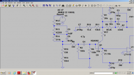
The 1u coupling cap was originally connected to V1a’s cathode but l moved it down to down to see if it would help. I’m running low on caps but I put 220p in parallel with the 47k input resistance and a 1k grid stopper at the 2nd stage, followed by a 470p cap to ground. This has helped the noise quite a bit but now the RIAA is off.
I have a few options to set the RIAA back to something more accurate, although I am not worried about absolute RIAA accuracy. I can change the first coupling cap to 100n, from 1u. Or I can move the 1u coupling cap back to the top valves cathode. Either of these corrects the bass a hump in the base response. The treble response is a bit out but this just needs another value other than 470p after the 2nd grid stopper.
This stage was inspired by Croft and their earlier phono stages that never seemed to measure well, had seemingly obvious design flaws but sounded great regardless. I think that that in hifi sometimes a little bit of imperfection adds a little bit of life into the music.
Im trying to think of a way to reduce the circuits bandwidth further without harming the response at 20khz too much.
The difference isn't only 1.5K, you are changing the way the stage work very deeply. Take some readings about SRPP's and µFollower, and in general, any series triode configuration in the web, or better, in a good book.How will changing the source impedance by 1.5k make a difference when the networks top leg is a 39k resistor?
its RA is half the ra of 12ax7 just the same gain...buy the 6n2p-ev with an OTK stamp on it(quality control).They have silvery anodes...easy to spot.
Member
Joined 2009
Paid Member
Yes around 40mA but with the tolerance you have to consider higher than this.
This is the revised stage. with some helpful notes. A bit of extra HF filtering. The PSRR is not great on SRPPs and while fairly quiet with a 10K load you have to crank the volume dial up a bit as and there is a little bit of noise. At some point I'll add some extra filtering on the PS. At 50K and 100K loads (see FR graph below - 10k, 50K and 100K loads) gain is much higher, so volume lower and mains noise is gone.


This is the revised stage. with some helpful notes. A bit of extra HF filtering. The PSRR is not great on SRPPs and while fairly quiet with a 10K load you have to crank the volume dial up a bit as and there is a little bit of noise. At some point I'll add some extra filtering on the PS. At 50K and 100K loads (see FR graph below - 10k, 50K and 100K loads) gain is much higher, so volume lower and mains noise is gone.
- Status
- Not open for further replies.
- Home
- Source & Line
- Analogue Source
- 12AX7 Phono Stage Susceptible to Surface Noise