I,m in need of some serious help.
I built this phono pre from China.
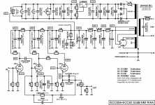
NEW E834 RIAA MM Amplifier Kit Base + Power Supply Kit + Transformer | eBay
I did a lot of research on this design and found at least 10 examples of its implementation. A google search of EAR 834 and several forums. In all the
examples I saw only good/great reviews.
My kit is not boutique quality but the parts are good. I'm using 12AX7LPS tubes.
The amp is not in an enclosure and properly shielded at this time so the "hum" is understandable. I will fix that when I get the amp to work properly.
I posted a request for help in this forum but did not get any workable answers. (wave form).
I noticed some slight changes from one schematic to another and I implemented some in my amp.
The amp seems to overload on higher volume levels.
Any help will be appreciated.
Thanks
I built this phono pre from China.
NEW E834 RIAA MM Amplifier Kit Base + Power Supply Kit + Transformer | eBay
I did a lot of research on this design and found at least 10 examples of its implementation. A google search of EAR 834 and several forums. In all the
examples I saw only good/great reviews.
My kit is not boutique quality but the parts are good. I'm using 12AX7LPS tubes.
The amp is not in an enclosure and properly shielded at this time so the "hum" is understandable. I will fix that when I get the amp to work properly.
I posted a request for help in this forum but did not get any workable answers. (wave form).
I noticed some slight changes from one schematic to another and I implemented some in my amp.
The amp seems to overload on higher volume levels.
Any help will be appreciated.
Thanks
Attachments
The amp seems to overload on higher volume levels
I'n not a valve guy, but are You using this pre with line level ?
It is intended for record playing. Small signal level.
The amp seems to overload on higher volume levels.
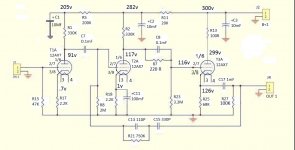
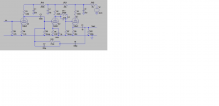
The RIAA network is of the Quad type, where there is no nfb at low frequencies, and the LF gain
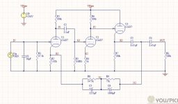
is equal to the open loop gain. I would use a different RIAA network that defines the closed loop
gain better, as in the fourth circuit shown. The later EAR circuit uses a jfet cascode input circuit.
What cartridge do you use?
Last edited:
I have a shure V15 III.
I will change the RIAA network as you suggest.
That should work fine. Use an input loading of 450pF, including the cables.
In the fourth diagram, if you choose NOT to use C3, make sure that the
voltage rating of the RIAA capacitors is 600VDC.
Hello All,
Thanks to Rayma (a very big thank you) My problem is almost fixed.
I rewired the feed back circuit as shown in schematic #4 (above).
The amp is working much better but the bass is being cut too much.
Now I just need to learn how to calculate the values.
Thanks
This is a common problem with tube global feedback RIAA circuits.
Theoretical values (that do not take into account the limited open loop gain)
will result in poor bass response. Trimming doesn't work very well because
all the values interact somewhat.
Now I just need to learn how to calculate the values.
Thanks
For this particular circuit you would be better off simulating or measuring. Not sure if precise calculation is easy or straightforward.
The amp seems to overload on higher volume levels.
It has crazy high gain, so if coupled with a high output cartridge probably becomes unusable with most line stages.
I've just simmed this in LTspice and the bass response is good into a 100k load, but drops off quite a bit with decreasing load impedance due to C3 (compensated to a point by the RIAA feedback network) and especially C4 (470nF). What load are you running this preamp into?Hello All,
Thanks to Rayma (a very big thank you) My problem is almost fixed.
I rewired the feed back circuit as shown in schematic #4 (above).
The amp is working much better but the bass is being cut too much.
Now I just need to learn how to calculate the values.
Thanks
As for the overload on higher volume levels, this preamp should be able to handle high output MM cartridges without any problems. A Shure V15III cart would be a piece of cake for this preamp. Is the cart set up properly and the stylus in good shape. Check your wiring of the preamp and that the voltages are correct. As I asked earlier in this reply, what are you driving with this?
Is the overload problem on both channels? And note that you are coming close to exceeding cathode to heater voltage rating (180V as per data sheets for 12AX7 & ECC83) of V3. As drawn in circuit #4, you have 145V on the cathode of V3. The heater of V3 will need to biased up to at least 65V or so, as I would like to see no more than a 80V difference between the cathode and heater... and add a diode from the grid to the cathode. Diode anode to grid, diode cathode to V3 cathode. A 1N4007 will work fine.
This preamp (circuit #4) has a gain of a little less than 35dB, so it shouldn't be of any problem. Not high by any means.It has crazy high gain, so if coupled with a high output cartridge probably becomes unusable with most line stages.

Thanks Cogsncogs for the information. I will study your suggestion for a while and see if I can understand the info and what changes I can make.
I'm using the pre amp to drive my computer sound card. I'm digitizing all my LP's.
One thing that I can't figure out is that the EAR834 amp has been on the marked for more than a decade. It's still being sold today. How is it that I can duplicate the exact circuit the designers put out so long ago and it not operate properly. I know components can make changes in the sound but to operate so far out of design is well above my pay grade.
thanks again
This preamp (circuit #4) has a gain of a little less than 35dB, so it shouldn't be of any problem. Not high by any means.
True. Never looked at this circuit. Why is it in an 834 thread when it has nothing at all to do with an 834?
Oh, i read the OP has butchered the 834 into this uninspiring concoction
My comments only relate to the pretty remarkable 834 circuit.
He doesn't need a mm phono stage with 50dB midband gain, and had terrible
overload problems, as would be expected. He needs a normal 34dB gain.
The EAR circuit is completely unsuitable for this, whether or not you like it.
For quite a while, the EAR has had a jfet cascode input, and this is not that circuit.
Last edited:
Please re-read my post #1 and look at the eBay listing. As far as I can see this amp is based on the EAR834. I built it just as the kit got to me, it had bad sound so I tried a few mods I saw online. Rayms’s suggestions got me in the ball park, just need to optimize the feed back network and all should be OK.
just need to optimize the feed back network and all should be OK.
Try 2530pF (2200pF + 330pF) and 1.62M for the RIAA, keeping the 750pF and 100k as-is.
It is also possible to short capacitor C3, and direct couple the RIAA network.
If the output is loaded by much less than 100k, I would increase the value of C4.
Last edited:
Member
Joined 2009
Paid Member
There’s tons of data on this amp, especially the version by Thorsten. My own version of the EAR 834P Clone
- Status
- This old topic is closed. If you want to reopen this topic, contact a moderator using the "Report Post" button.
- Home
- Source & Line
- Analogue Source
- HELP, I,m Desperate!!!!!